No Problem hooking up the drill motors, We’ve done this many times just never through a vex board.
How would you connect it?
No Problem hooking up the drill motors, We’ve done this many times just never through a vex board.
How would you connect it?
Still to early to tell - you haven’t answered my previous question.
Please keep in mind this is just guesswork. It may in fact not be a PWM signal, and attaching it to your Vex may damage the custom board and/or the Vex. It is also somewhat likely that the two control signals could be analog potentiometer inputs.
You say that you’ve used this before just not with Vex. When you’ve wired it up in the past, what did you wire it to?
Also, how many motors does this board drive? (I’m assuming two).
Black = MC 1-2 GND
Yellow= MC-2 FWD
WHITE= MC-2 REV
RED = MC 4-2 PW
It was for 2 motors to obtain tank drive. It was connect directly to the receiver to a FUTUBA receiver, normally on CH1 & CH2 with the wires being split between both channels.
Looking at the Pictures, and a little Google Search with “electronic services” “motor controller” pic, got me this page as the first item, Diverse Electronic Services.
It looks like the MC-7 with a PIC Daughter Board…
I think I am going to add a note about “SHARP AND CLEAR” Digital Photos are the best…
attached with a RCIC2_SC microprocessor
Excellent. Based on that link, it looks like you would do the following:
[LIST]
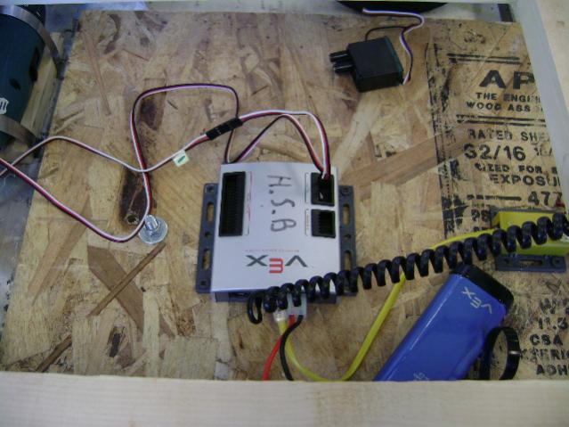
*]Red: Leave unconnected. Normally this is used to power the receiver, but the Vex Microcontroller has its own power source.
*]Black: Connect to the outer pin of motor port #1 (outer pin means the one furthest from the keying tab on the port socket)
*]Yellow: Connect to the inner pin of motor port #1 (inner pin means the one closest to the keying tab on the port socket)
*]White: Connect to the inner pin of motor port #2.
[/LIST]
You will need a pair of Male-to-male servo extenders, or three of those M-M SparkFun jumpers I linked to in my post above. Or you could cut a pair of standard servo extensions and wire the cut end directly into the screw terminals on the PC board.
If you are driving this just via remote, then you will want to set up the remote for tank drive (23 mode), though it will operate like arcade drive because it has a channel mixer built in (if I read the specs correctly). That means you’ll just use the right joystick to drive it. You may have to reverse either or both channel 1 and channel 2 on the remote, depending on the way your motors are setup.
If you are driving this from software, you will set the steering value on motor #1 and the speed setting on motor #2: Setting motor 1 to 0 will steer hard one way, 255 will steer hard the other way, and 127 should steer fairly straight. Setting motor port #2 to 0 will be full reverse, 127 will be dead stop, and 255 will be full forward. Numbers in between these extremes should provide a proportional amount of steering or speed.
Keep in mind that hooking this to your Vex microcontroller will probably void the warranty, though I don’t see any reason it would be a big risk.
Good luck,
And so it is!!
That is a fancy price for the MC-7 and RCIC2_SC.
(Honestly, I was amazed to read as much off the circuit board as I did to make the Google Search.)
DEAN, your the MAN!!!![]()
THANK YOU EVERY MUCH FOR EVERYTHING. And also a BIG thank you to Marko, without him i would’ve have founded the circuit board ![]() I JUST HOPE IT WORKS
I JUST HOPE IT WORKS ![]() hahah i’ll keep you posted.
hahah i’ll keep you posted.
Now, we have to detele everything so no ones see this :D, lol
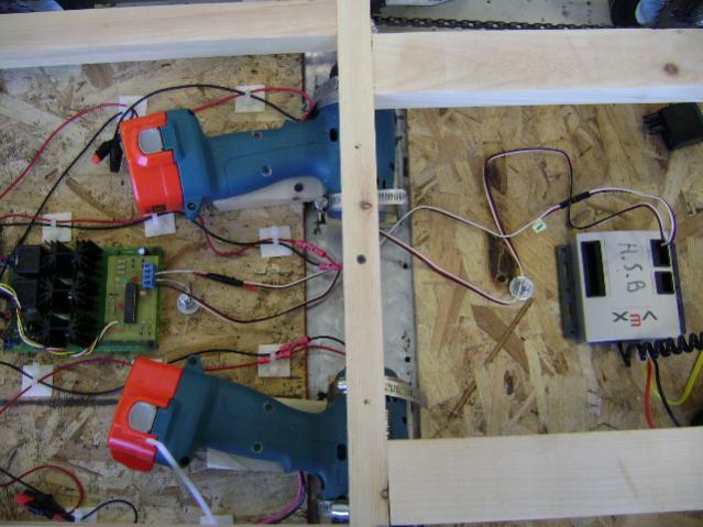
I used the Diverse Model MCIPC-24 Motor Control Board, some 24 Volt relays and the VEX Controller to drive two 24 Volt Swiss Geared motors on EarthBot shown in the VEX Gallery.
https://vexforum.com/gallery/showimage.php?i=1871&catid=member&imageuser=392
Glad to help, but much of the credit goes to MarkO and rickyd31 for the product links.
Hopefully it’ll “just work” ![]()
Cheers,
Connected everything the way you said but it doesn’t seem to be working. The circuit board has power but there is no signal coming from the VEX to the circuit board. Any ideas??? I have attached a picture of our set-up to help us figure it out.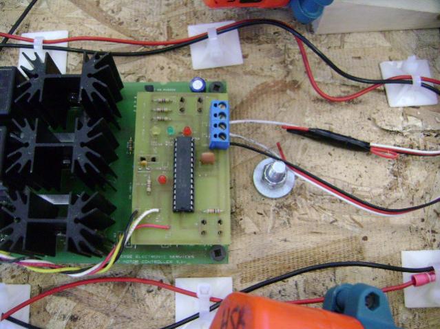
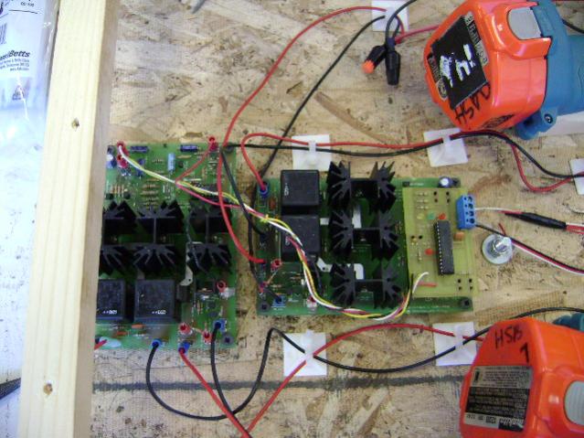
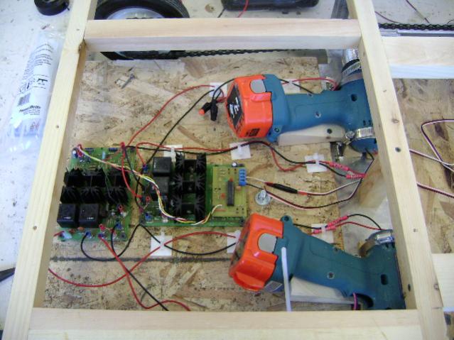
It is hard to tell, but it looks like you’ve plugged your connector on motor port 1 backwards. White should go toward the keying tab/slot.
When diagnosing problems like this, the first step is to isolate the problem. First, I’d unplug the 2 cables and attach real Vex motors to ports 1 and 2. Then verify that they run as expected when the joystick is moved. This will clear everything from the joystick operator down to the Vex microcontroller. Second, I would try to hook the motor drive boards up to the R/C receiver just like you used to do and verify that works like it used to. That will clear the motor boards, motor wiring, and motor battery.
If all that works, then we just need to double-check the custom Vex-to-motorboard wiring (my analysis of the spec sheet, as well as the physical connections). If that checks out, then we have to figure out what the difference is between the signal coming from the R/C receiver and the signal coming from the Vex.
Cheers,
Some questions regarding your connections:
Did you build the 2X Amplifier Interface board that boosts the PWM control voltage output from the VEX Controller PWM adapter cable from 2 to 4 Volts to 6 to 8 volts. Diverse provided a schematic and it worked on my Earthbot fine using either the Parallax Stamp BSX or the VEX Controller.
Did you connect a PWM adapter cable ($10 from IFI) to the VEX Controller motor output? You cannot connect the VEX SERVO or VEX MOTOR outputs directly since they do not generated the necessary signal levels.
Did you connect a 4.7K Ohm resistor across the POT terminals and also connect the PWM output to the center (wiper) connection.
Did you test your circuit using a POT instead of the VEX Controller?
He appears to have an RCIC2_SC interface board attached to the MC-7s, so I don’t believe any this applies to his rig. The RCIC2_SC handles all the requirements of driving the MC-7, and takes a pair of standard R/C PWM pulses as input.
Cheers,
hey, thanks for everything and trying to help me solve this problem. I’ve found out that we weren’t allowed to use another U controller /U processor. There’s another way to do it with a speed controller and an off center 3 way switch and that’s good now.
Thanks everybody for the help, and i’ll chat with you when i have and other problem ![]()
Small questions, can you use a non-vex servo in the CPU? i just need to change the female connection to male?
Yes, as long as they have the same pin out.