My team burned 3 ports on the brain in one practice session their first year (Tower Takeover). After some thinking and analysis, we developed a strategy to resolve the issue.
The robot for that season had a DR4B lift with a claw on the end of it. The blown port was connected to the claw motor (at the top of the lift). This motor blew 3 ports in one practice (they kept re-assigning the motor to keep going…).
My analysis is that the standard VEX bearings are made of a non-conductive plastic. As a result, rotating linkages are electrically isolated from the main chassis of the robot and the brain. The standard engineering solution to this sort of problem is to electrically bond the parts. Unfortunately, VEX does not sell bonding jumpers (short wires with ring terminals). Fortunately, you are allowed to use commercial items for bundling or wrapping of cables (<R8> (f) this year).
We used a braided metal sleeve (designed for protecting hoses and wires) around the cables, zip-tying it snugly to both the claw (where the motor was mounted) and the frame (where the brain was mounted). This completely resolved the fried ports. We successfully used a similar strategy during Change-Up. They built a tether-bot with a 12+ foot cable bundle between the halves, fed through a braided metal sleeve. Again, they never fried a port.
My suggestion to VEX is to offer one (or both) of the following products:
Shielded smart cables (with either a 5th drain wire or a shield conductor connected to ring terminals). This would allow teams to electrically bond remote structures to the main robot frame.
Electrical bonding wires (short lengths of stranded cable with crimped ring terminals). These could be used to electrically bond around insulating bearings.
Obviously, the bonding wires would be the easiest to implement.
Either of these solutions would allow teams to utilize best practices and electrically bond their structures together for ESD mitigation.
I guess, the silver lining here is that students not only learn firsthand about the static electricity effect on electronics but, also, about the practical ways to mitigate it, since appropriate protections are not present in V5. Which should make them better engineers!
However, I wish VEX led by example. It has been very frustrating (vexing, may I say) after all these years to see them unwilling to acknowledge design deficiency with V5 in regards to handling ESD and, either fix it with hardware update, or make it legal for students to do so themselves.
I don’t know about others, but it certainly kept me from ordering any additional V5 electronics, waiting for ESD protections to improve.
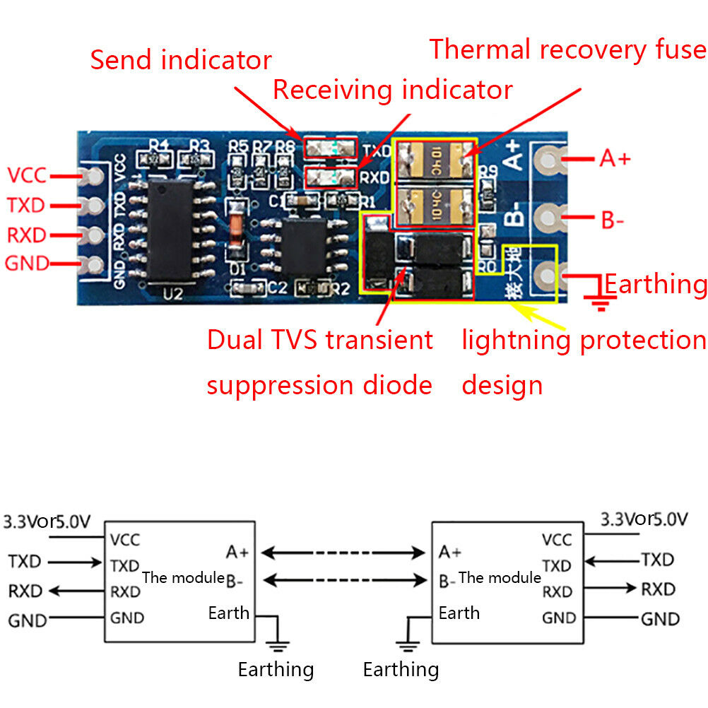
Coincidentally, just a few days ago, I have ordered a couple of RS485 to TTL modules to communicate with a wired outdoor gizmo, and they were dirt-cheap $1.47 apiece with free shipping included.
Even if it has off-brand TVS arrays and thermal fuses - they still offer better protection for the 485 driver chips than having none like in the V5 Robot Brain. I am pretty sure that, if VEX wanted, they could add similar parts to V5 at way less than $1 per channel.
Even if it still makes financial sense to replace every failed $275 brain (+at least $25 in s&h) rather than adding $10 to the BOM per unit (assuming less than 1 in 30 failure rate requiring replacement), I still don’t understand how it makes engineering and marketing sense to keep making such fragile product that keeps giving bad rap to your brand.
Ha ha ha we learned and we learned about the stupid ESD, alas we are not geniuses yet as ports still burn, no matter how much we learn about it and no matter how much we mitigate. Still bozos. LOL. And by the way, we always reference your awesome collection of posts and we learn from that too so thanks!
Tried that too then started thinking about the theory of it and realized that the components we are trying to bind electrically are actually isolated through their mounting system so no matter how we link the metal structures, we will never create a common ground because the brain mounting holes are electrically isolated from the main board and so are the motor mounts, those are just metal inserts that sit in a plastic casing so the only connection between the electronics is through the cable and never through the robot chassis. Is this wrong?
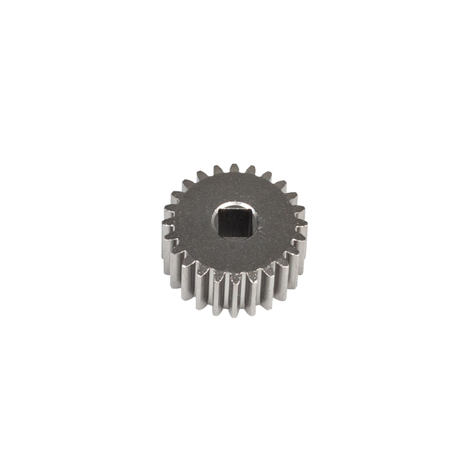
These gears are now available for purchase from the US VEX Robotics store, and will be available internationally in the next few weeks as our other offices receive inventory.
I can only spell CAD and wasn’t able to figure it out on the product page, but would there be enough room on the face to be able to drill a hole that could accept an 8-32 screw (either straight thru or tapped)?
I imagine these won’t pair very elegantly with the other gears because the diameter is not necessarily in half-inch increments. I could be wrong since I haven’t checked in a CAD file or anything. Anyone want to check? Still, a very neat part that will allow for a greater range of gear ratios.
To remedy this, you can install a nylon bushing held in by friction (drill out a hole to the match the correct OD of the spacer). It’s legal since it’s technically just a spacer. It’ll give more stability to the joint while allowing low friction free spinning
All V5 gears are 24DP, which means there are 24 teeth per inch of pitch diameter. So a 12T gear would have a pitch diameter of 1/2" (12T / 24DP). The 24T gear would have a pitch diameter of 1". The pitch diameter of all the V5 gears are:
12T = 0.5" Pitch Diameter
24T = 1.0" Pitch Diameter
36T = 1.5" Pitch Diameter
48T = 2.0" Pitch Diameter (this was part of the EXP announcement)
60T = 2.5" Pitch Diameter
84T = 3.5" Pitch Diameter
As long as the pitch diameter of a gear is divisible by 0.5", there will be no problems with it playing nice with other gears in the system.
But to work with the existing holes in Vex metal, the radii (not the diameters) of two gears have to add to a multiple of 0.5". 12T + 12T works because their radii add to 0.5" and they fit in consecutive holes. 12T + 36T radii add to 1.0", or two holes apart. 12T + 24T gives you 0.75", which will be halfway between two holes. There’s a reason why all the gears up to this point have been odd multiples of 12T.
I guess the 24T and 48T gears will work nicely together, though.
This is an opportunity for some fun new VEX products: High Strength pillow block bearings
Ideally, they would make 2 versions:
One version that centers the shaft ON the holes of the supporting metal
A second version that centers the shaft BETWEEN the holes of the supporting metal
Obviously, the upper option would likely be 3 holes long, while the lower would be 4 holes long…
Edit:
There is actually a third option:
Make a single version that offsets the shaft by 1/8" from the holes. If both blocks are offset the same way, then the spacing is a multiple of 1/2". If they are offset in opposite directions, then the spacing is an odd multiple of 1/4".
This would allow more versatility at the cost of a little installation complexity…
@Bob_Mimlitch_III Considering the GDC has once again ruled the community’s solution to this problem (BLRS’s ESD protection boards) as illegal, I think a response to @Andrew_Strauss’ post is in order. I have linked it below: