Resistive load or not, it’s all the MCU in MC29 that decides. The waveforms @jpearman measured show that even though the Cortex PWM output is quite linear all the way to 127 (with 2.14ms PWM pulse width), the MC29 takes anything over 1.92ms as “full steam” and the output timing of the H-bridge (even though still not kept open 100% of the time) doesn’t change anymore. I could try to verify this by measuring at the gates of the H-bridge FETs to remove all the doubt, but the consequence is, MC29 totally isolates the motor from the information whether the input PWM was over 1.92ms and how much.
Which port? I am not discounting your observation, but there are several possible explanations that aren’t contradicting the “84 is the information barrier for MC29” claim.
I was able to dig up some data from NbN season, and turned out my memory is not that good.
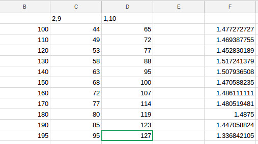
We had 3 motor flywheel - two motors connected to ports 1 and 10 and remaining one to MC29. The following table was constructed when only two of the motors were running and the third was serving as the passive load along with the flywheel. Our target RPM for full court shots was 180 (out of max 240 for turbo motors). The test was done with slightly discharged battery but at constant voltage.
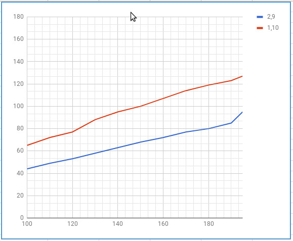
Column B is the target RPM, column C is power required to achieve that RPM when motors are connected to ports 2 and 9, and column D corresponds to motors on ports 1 and 10. Column F is the ratio between power levels on different ports.
Turned out the motor control value vs output speed were pretty flat under the load:
I looked into our source code and “learned” that we were scaling power level going to MC29 at 1/1.45 of the power level going to ports 1 and 10.