I would like feedback on my drivetrain (6 motor, chaining 2 11 watt and 1 5.5 watt together)
Because of the 55W motor restriction, I designed it with:
4 x 11W (running at 200 rpm) motors and 2 x 5.5W motors
5:3 gear ratio
2 omni wheels and 1 traction wheel per side (all 3.25")
The current CAD is not completely finalized, I plan to add at least one more brace when I build it, but I’d like feedback on the design as it currently stands.
Some specific areas I’m interested in hearing about:
Potential structural weaknesses
Voltage control through PID - is it reliable? how hard is it to program? do the motors heat up fast?
Weight distribution and traction
Motor usage and efficiency under the 55W limit
Anything that might become a problem during competitions
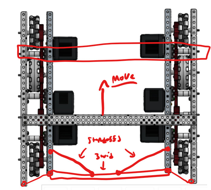
I like the cad and am glad you acknowledged the need for another brace or two!, I also just want to potentially propse to you, how you are going to make sure your drive is squared well, whether that be through structural screwjoints, standoffs, shoulder screws etc!
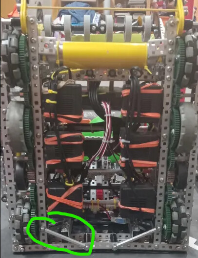
i would move this cross brace forwards and then brace across back with standofs triangle and then 3wide across back verticaly. make sure to triagle brace it as well.
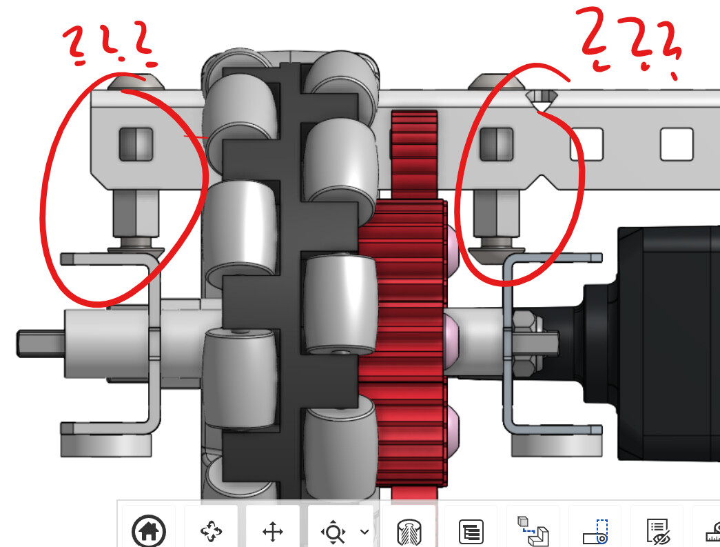
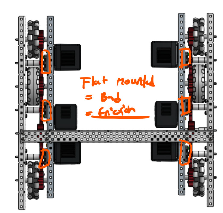
all shafts that have a motor on them dont need a bearing on the motor side. this is called flat mounting. you dont need this bearing because the shaft already alligns to the motor cartrige so its constrained by the motor and if you do have the bearing then you cause mis alignment between the motor and that inside bearing increasing friction. KEEP THE ONES ON THE OUTSIDE only remove the ones on the motor side.
Something I have come across is that by using voltage control, you can actually get your motors to run faster than their listed specifications. The 5.5W motors/ 200 rpm motors can actually run closer to 300rpm. From the information in the original post, I gather it was 333rpm on 3.25" wheels. If you use voltage control that ends up being 500rpm, which is probably too fast. Make sure not to use voltage control or you will end up much faster than you expected!
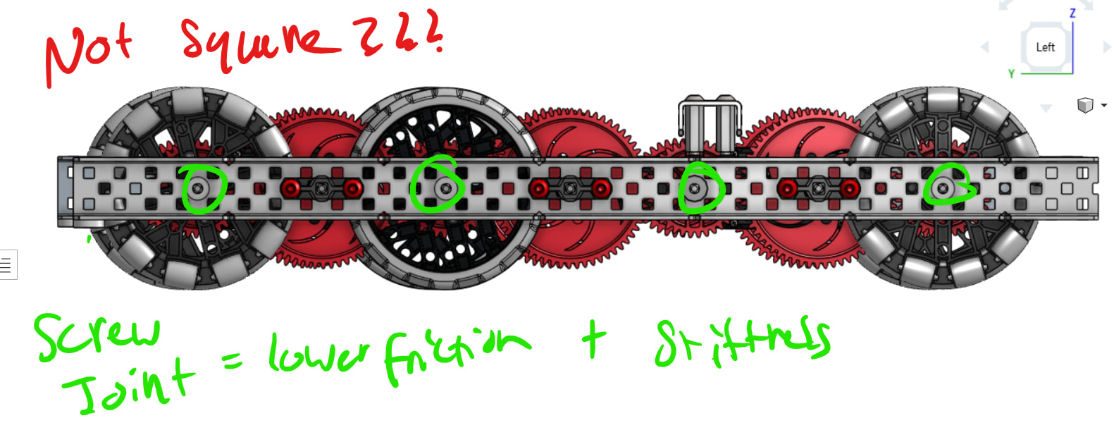
Sorry for being so slow, I was doing exams, by squaring across the drive c-channels it will ensure verything is 100% parallel, a product of doing this will be the fact that your robot will have reduced friction!
I seem to remember you filming a robot reveal video… Anyway @LeoT-10743B is definitely right - adding more crossbraces would help a lot in stopping your drive from flexing. I would also recommend using shoulder screw to help keep everything aligned, but this isn’t entirely necessary.