Is that six-motor drive or are the motors facing inward for something else?
this is a building technique where you take standoff coupler set screws, and thread them into the screw hole of shaft collars. Then you can tighten the standoff onto the shaft collar, and mount the shaft collar to something else through the main hole.
I see! That’s really cool–thank you so much for sharing!
6 motor drive! (we really recommend)
we use 1.625 30A initial intake wheels, and 2 inch 60A secondary rollers
it’s a nice thing to know how to do, but try not to get carried away with it. when I first discovered this technique I spammed it everywhere, and it added a lot of weight and made things annoying to assemble. In many cases, a piece of 1x1 angle does the job better. Just something to keep in mind if you or anyone else wants to start using this technique.
What do you think about this case?
Wouldn’t do it personally. the structure at the end of the catty arm really doesn’t need to be very strong at all, and you want it to be as light as possible to reduce inertia of the arm so it can accelerate more quickly during launch. The use of 2 3 wide channels, 2 plates, multiple standoffs and shaft collars, and the screws/nuts that follow are going to make this pretty heavy. If I were to build a catty, I would try to make the launch pad (hand, cup, whatever you want to call this part) out of polycarb with just a few standoffs to mount it and retain the discs.
I understand… We were considering a catapult just because it’s so easy to build, and so this is all very good to know. I don’t know if anyone has told you this before, but you really are very good at this!
we will also take this into consideration -_-
Thinking about it now, I agree, I’ll look into making this lighter. thanks for the non direct help? but fr 99999v pog
another quick update, as of now we don’t have any triangular bracing for the roller mech, but it is working actually quite well without, we are still considering adding it though
What’s the benefit of using axels instead of screws for the wheels in the drivetrain?
there’s no benefit it just makes it easier for us to construct as we don’t have to attach the gears to the wheels.
you’re not worried about slop?
regardless of what type of joint you use, it’s still a good idea to bolt wheels to gears. This is so the power isn’t transferred through just the shaft, which over time can wear out the square inserts and the shaft, and will have a bit more slop.
okay after building everything and modifications to a few things, you weren’t wrong. it sucked trying to get it to work. but, it works now.
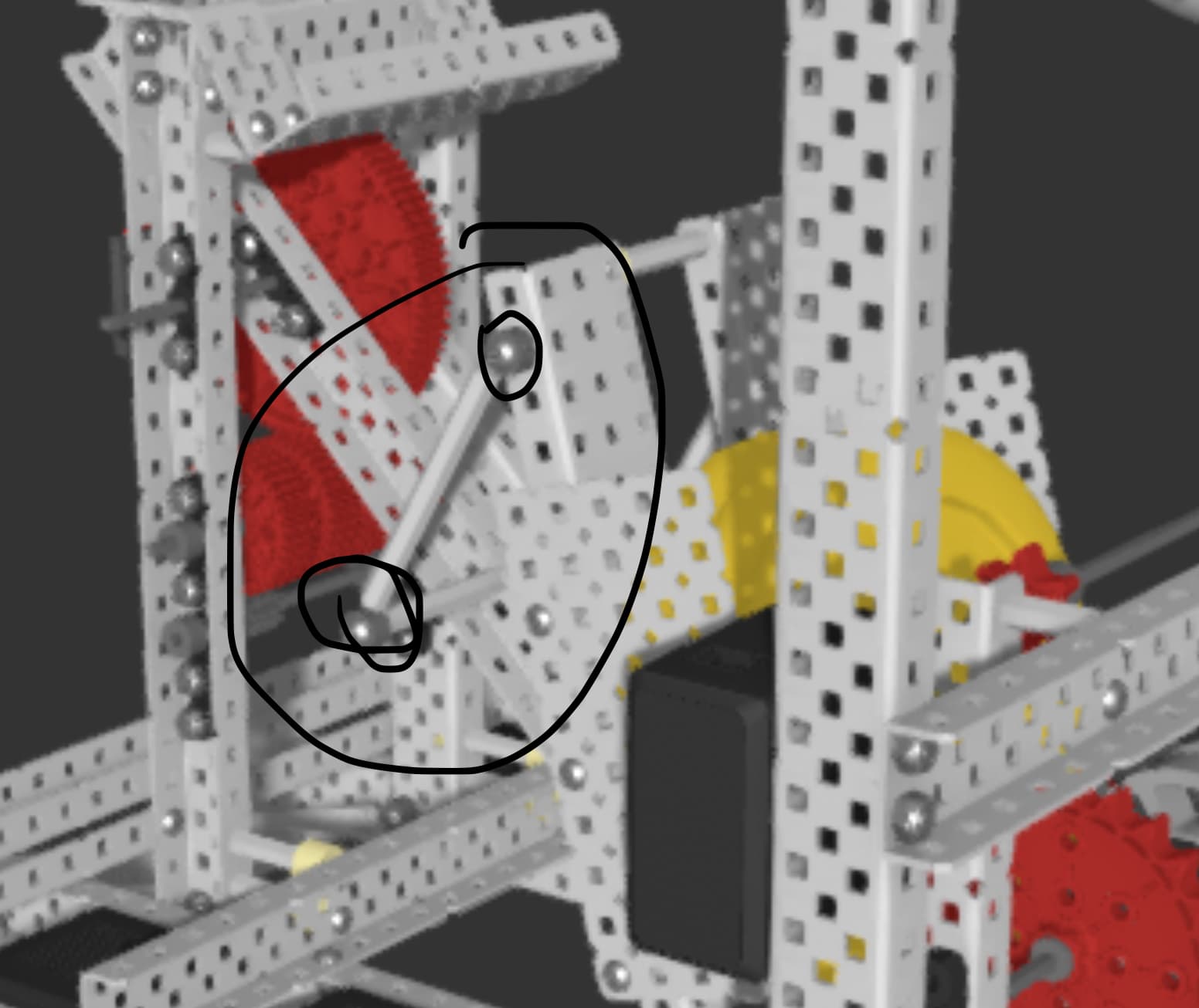
Where would you put the rubber band in order for the catapult to launch the disks? a diagram would be helpful, thx!
depends on your design. I don’t recommend copying this robot as it isn’t the best, I do recommend seeing this design and innovating it to your ability tho. build something that comes to your mind. it’ll be so much better in the long run.
In very basic terms, find two points that are close together when the catapult is in its fired, or more vertical position (what it would look like after its fired a shot), and far apart when the catapult is in its primed position (what it would look like before its about to shoot) and then put your rubber bands across those two points.