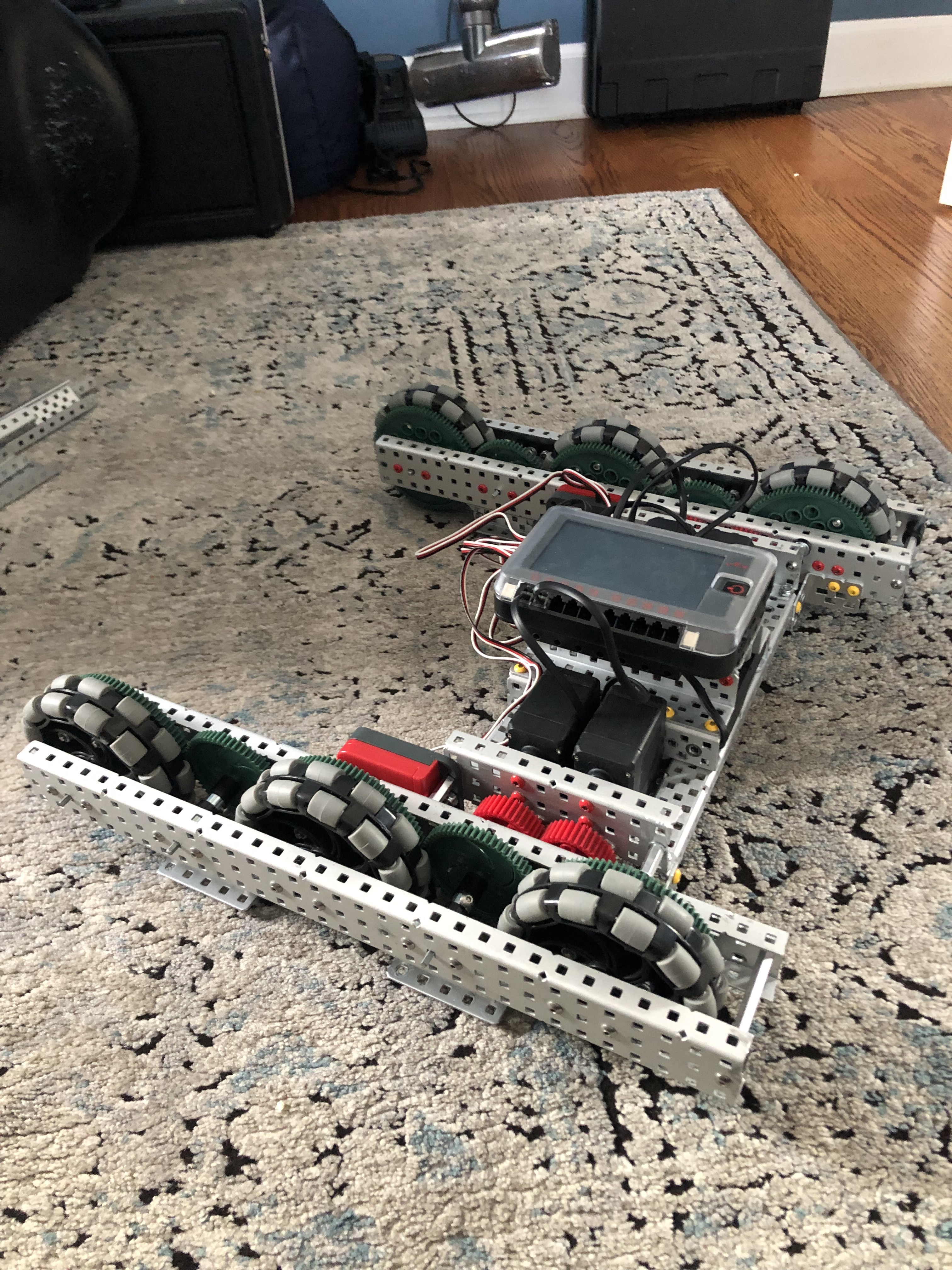
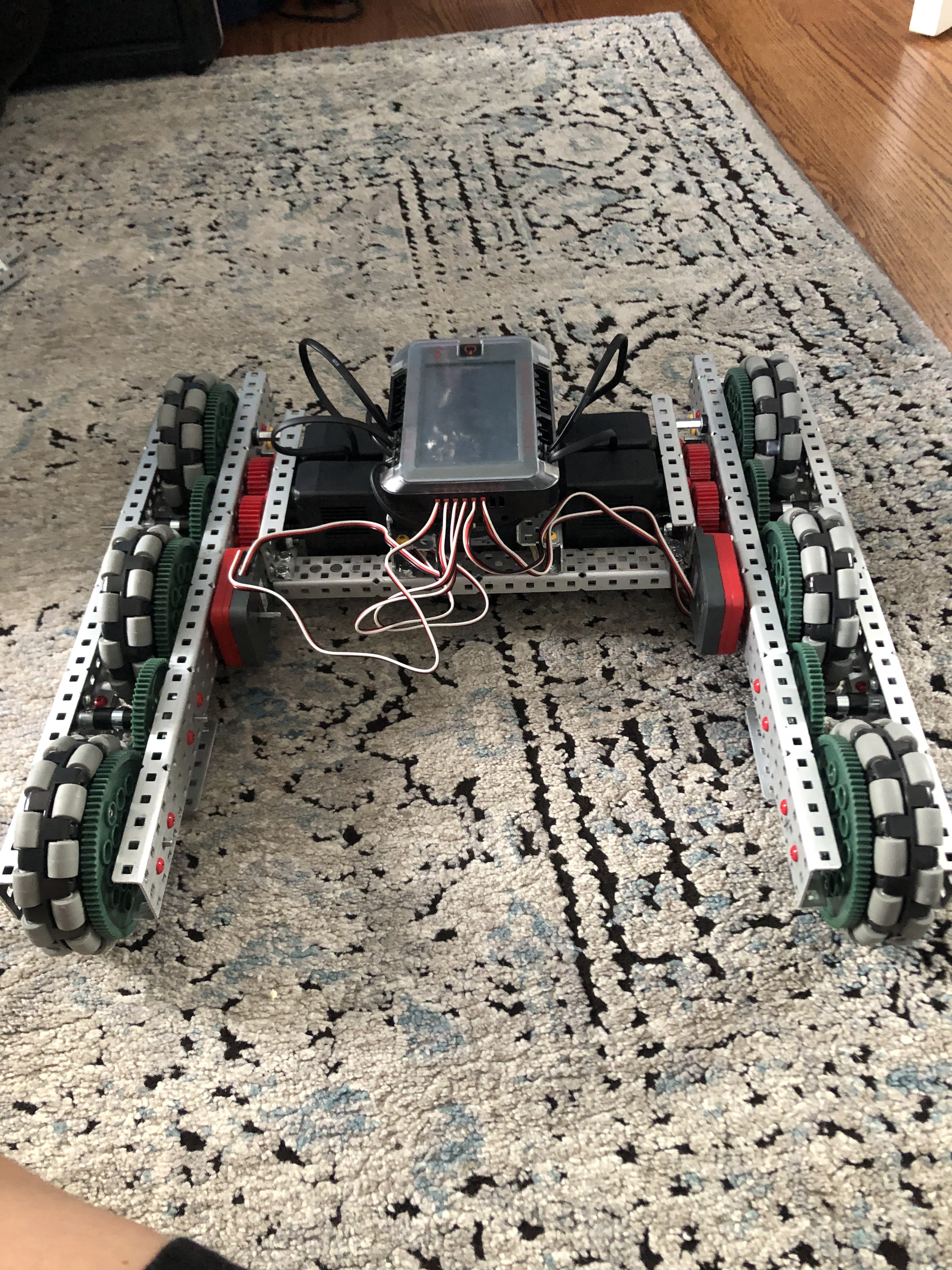
I have completed the drivetrain I plan on my team using for Over-Under, it is a tank drive with a total of 6 wheels connected to the motors via a system of gears. I implemented an odometry system within the chassis as well, but the way I did it was by connecting 2 of the 3 shaft encoders directly to an axle that is connected to one of the 6 driven wheels. The other shaft encoder is connected to a dead wheel. I am concerned that there is something I am doing wrong here, because all of the odometry systems I have seen teams use are connected to exclusively dead wheels. I’m not an expert on odometry or anything, so I don’t know if this is something that isn’t a big deal or will ruin the odometry system.

The issue with attaching odometry encoders to driven wheels, and the reason that most teams use passive “tracking wheels” is because of wheel slippage. When the motors on your drivetrain send power to the wheels to turn them and in turn move your robot, there is a decent chance that the driven wheels will not grip the surface of the field tiles perfectly and will slip some amount. This rotation of the wheel without a corresponding movement of the robot will introduce an error into your odometry calculation which can compound very quickly into a sizeable error in your position. Therefore it is best to use undriven wheels for which the only resistance against the tiles will be their own inertia, which will have negligible slippage if done correctly. It’s worth noting that this is merely one component of building a good and accurate odometry system, and that for small movements or small time slices it may be simply “good enough” to utilize encoders on deiven wheels for odometry calculations.
Adding on to what sazrocks said, there is no right way to do odometry, only a most accurate way. Using seperate dead wheels on a hinge to maintain constant contact with the ground will result in the greatest accuracy by reducing wheel slippage. On the other hand, if you don’t need your odometry to be as accurate, it is possible (though not recommendded) to do odometry using only the motor encoders and no external shaft encoders. The decision ultimately comes down to how accurate you need your odometry and whether you have space to implement seperate dead axle wheels.
Thanks for the help! Seeing as Over-Under includes jumping over an obstacle, I don’t think it would need to be extremely accurate to be effective considering all the error that comes with going over the obstacle. I was wondering though, if the amount of wheel slippage could be measured and the error removed using the inertial sensor. If the odometry system’s measurements are ignored until the inertial sensor senses movement or something like that, would the error be removed from the odometry system’s measurement? I don’t know exactly how accurate the inertial sensors are, or if there is a significant delay between the robot’s movement and the inertial sensor picking that movement up, but if it eliminates some error in the odometry system it could be helpful to use. Also, do you know if the amount of wheel slippage is mostly consistent or random, because a consistent amount could just be ignored in the code.
I suggest you look at FTC for some inspiration this year. We had to do this in 2021. This explanation goes into some detail, but I’m sure there are some posts that show all of the tuning we did as a community. (I don’t have the links on me right now and I cannot get them as I am on a school Chromebook ![]() )
)
The issue with this is it is hard to distinguish between moving forward at half speed with full traction, and full speed with half traction, they will move the robot about the same, but the latter will make the robot think it is way farther forward than it actually is.
Removed? No. (Odometry as a physical component always has errors) Reduced? Maybe. for this idea to work I imagine you would need a table of speeds and sensor measurements to call upon in your code, but you might be thinking of a different way to do it.
Wheel slippage is mostly reliant on jerk, which is a derivative of acceleration. Yes, you could tune it out, but most likely if you are doing odometry right, and implementing the right solutions to your problems into your code, you really should not need this, it might help to get mm accuracy, but unless there is something seriously wrong, I would look over this for now. If you are not using PID, or just sending your drivetrain off at 100% Velocity at the start of a motion, then you might want to look at wheel slippage a bit more, but your time at that point would most likely benefit more from getting a PID loop or a motion profile (or both they work great together)
This is not practical.
Wheel slippage tends to be “random”, but you’d imagine that it happens on high-acceleration movements (i.e. starting and stopping quickly).
In general (and even more so with this setup) you will be far more successful using an IMU for heading and two perpendicular tracking wheels than with the three tracking wheels you have now.
The wheels need 100% contact with the ground at all times for them to act as tracking wheels, which is why separate tracking wheels (se 606x for an example on youtube) become a necessity.