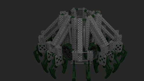
For the Clawbot design contest, I went for the “Octo-claw” bot style. The robot ended up with 16 claws, 2 per arm. 2 motors would be used to control the arms and claws, and 8 motors would be put towards the drive train.
[ATTACH]6361[/ATTACH]
For the movement and opening and closing of the arms, we reduced the motor count down to only 2 motors for all 16 claws. How? For the movement, I figured that there only needed to be two positions, “Trough” and “Ground”. So using a 4-bar on each arm, we could use a piston to control from resting on the ground to 18+in in the air. Now to control each individual claw, we researched and found an interesting mechanism called a “Multiplexer”. Pretty much how it works is that you have a driving motor and then a motor that moves a gear to link the driving motor and the desired output together. In theory, you could have infinite arms controlled by 2 motors.
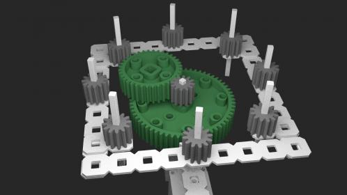
Here is a very basic image of the multiplexer. Each of the 8 outer 12-tooth gears are the outputs. The middle 12-tooth gear is the driven input. The 60 tooth gear and the 36 tooth gear are attached, the 36 tooth gear can spin freely. As the 60 tooth gear spins, it moves the 36 tooth gear in circles, connecting the middle driven gear with the outer gears.
[ATTACH]6367[/ATTACH]
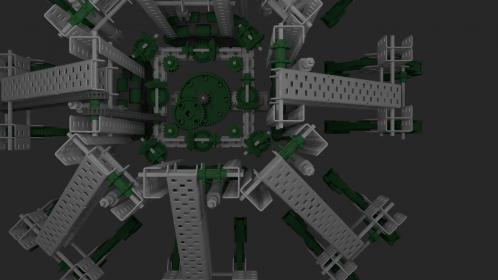
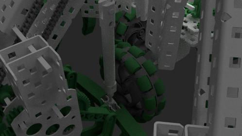
In order to attach the outputs to the arms, bevel gears are attached to the 12-tooth outputs to convert from horizontal gearing to vertical gearing. Then the vertical gearing can be chained together to eventually go down towards the claw.
[ATTACH]6364[/ATTACH]
Thanks! ![]() I’d like to hear feedback from everyone! Note: This is only a 80% CAD drawing (obviously the drive base, controller, pneumatic supplies, ect were nearly ignored). If a more professional/complete drawing is wanted I can make it, it’ll just take a lot more time. Also if I didn’t really explain something well, which is likely, just give me a head up and I’ll try to re-explain/post closer-up pictures.
I’d like to hear feedback from everyone! Note: This is only a 80% CAD drawing (obviously the drive base, controller, pneumatic supplies, ect were nearly ignored). If a more professional/complete drawing is wanted I can make it, it’ll just take a lot more time. Also if I didn’t really explain something well, which is likely, just give me a head up and I’ll try to re-explain/post closer-up pictures.
Another Thought: For ease-of-use reasons, you could put an LED on the top of each arm and then use a 3-bit electronic multiplexer to show which claw is being controlled. Using the electronic multiplexer could reduce the needed analog/digital ports from 8 to 3.
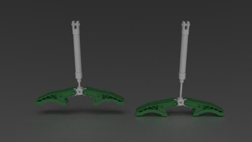
EDIT: I thought of this after I posted it. I saw a thread about how people wanted to make brakes on their robot… I know the claws have rubber ends, why not make them brakes!
[ATTACH]6370[/ATTACH]
Here is a picture of them in context of the robot
[ATTACH]6373[/ATTACH]