Many teams are running into V5 limit of just 8 legacy ports, and even the Cortex hardware with 13 digital and 8 analog ports may not be enough for some of the teams.
So what can be done?
First of all, Cortex users that run out of digital ports but have unused analog ports could simply connect buttons or limit switches to the analog ports.
Second, if you use multiple quad encoders, and don’t care about direction of rotation but only total tick count (for instance with flywheel) then you could plug only one quad encoder output and leave another wire unplugged.
Another option for those who likes to use a lot of limit switches would be to simply Y them to a single port. For example, if you only use them to calibrate one subsystem at a time and always know what motor you are running at any moment.
Unfortunately, a simple Y solution will NOT work if multiple switches or buttons could be pressed at the same time. However, there is a workaround.
Some of you may be familiar with Arduino oneWireKeyPad library that allows to read multiple buttons using just one analog port. It works great when you expect only one button to be pressed at a time, and will let you determine which button was pressed.
Then, for cases where multiple buttons could be on or off at any given time and you need to know exact state of each of them, there is a R-2R resistor ladder method.
For example, this is an instructable with slightly different implementation, but pretty much using the same concept: https://www.instructables.com/id/How-to-access-5-buttons-through-1-Arduino-input/
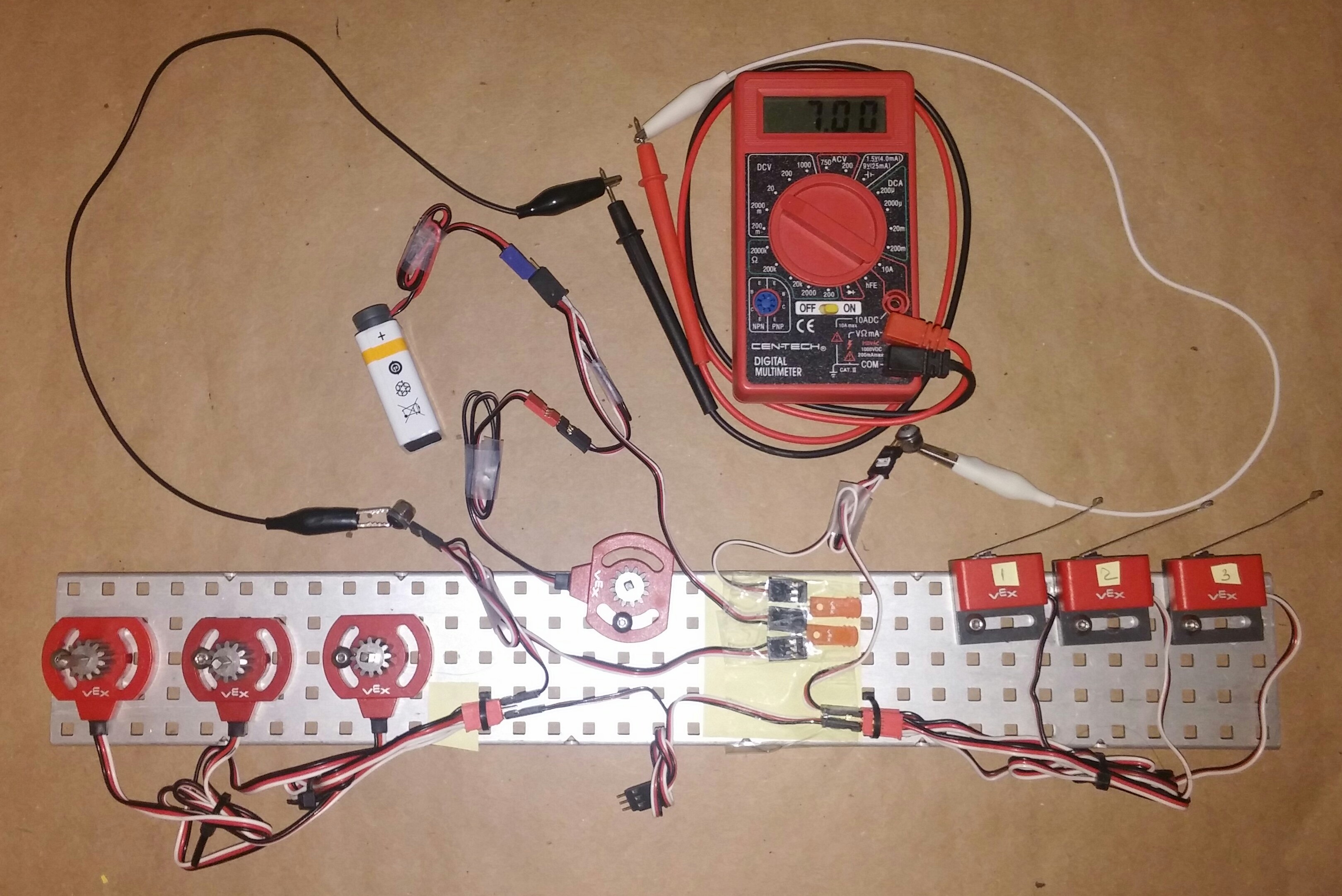
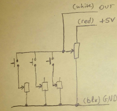
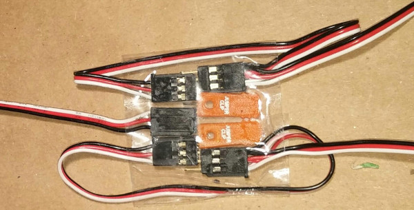
It is possible to have similar solution with only VRC legal parts. Attached is a picture of the circuit that allows to use a single analog port for reading the state of multiple limit switches. In addition to switches, you will need 4 Y-cables, 2 orange jumpers, and 4 potentiometers. If you want to add three more switches on the same port you will need 3 more Y cables and 3 more potentiometers.
The top Y-cable (that is connected to 9V battery) would be normally plugged into the Cortex or a legacy port on V5 brain. It splits into connection to a master (top) potentiometer and to the orange jumpers that connect black wire to the ground rail (Y-cable on the left) and white data wire to the output rail (Y-cable on the right). I made those rails by gently clamping metal pins of the Y-cables between metal washer and nylock thus electrically connecting all six female ports on both ends of those Y-cables. There are plastic washers under screw heads to take the bulk of the compression force and protect the pins.
Then each limit switch is connected in series with one of the potentiometers (through the bottom Y that serves as the three F-F jumper wires) and then all of those pairs are connected in parallel between ground (black) and output (white) rails.
First, I tuned top master potentiometer to provide 7v output out of 9v supply voltage, when no switches are active. Then I tuned pots on the left such that output is 5v when first switch is pressed, 4v when the second, and 3v when the third. Here is the full table:
Pressed   |   Output
--------------------
none            7v
1               5v
2               4v
3               3v
1,2             3.3v
1,3             2.57v
2,3             2.28v
1,2,3           2.02v
You can see that values are getting closer when multiple switches are active, but even if you connect six of them and properly tune potentiometers there should be enough resolution in the 12-bit ADC to reliably read any combination of switches.