I’m going to try and explain why we sometimes have problems with the pneumatics firing and why different programming options are behaving differently. To understand what’s going on some background knowledge is needed on how the digital IO ports are configured by firmware and what features the specific micro controller in the cortex has.
To start, lets look at the simplified schematic of a digital IO port from the cortex user manual.
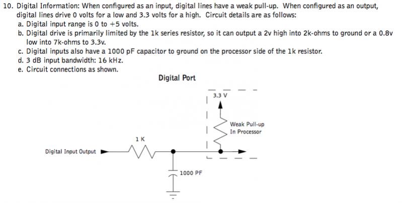
This shows the 1k ohm series resistor that’s used as short and ESD protection, a capacitor connects the IO port to ground to help with noise suppression and a weak pullup resistor is shown inside the cortex. A weak pullup is a resistor with a fairly large value, it can be overridden externally by using resistors of significantly lower values, for example, if the weak pullup was 100k then a pulldown of 10K would force the pin to a value of 0.3v, essentially grounding the input.
Next lets look at the details of the digital IO port inside the cortex (specifically inside the STM32 user processor).
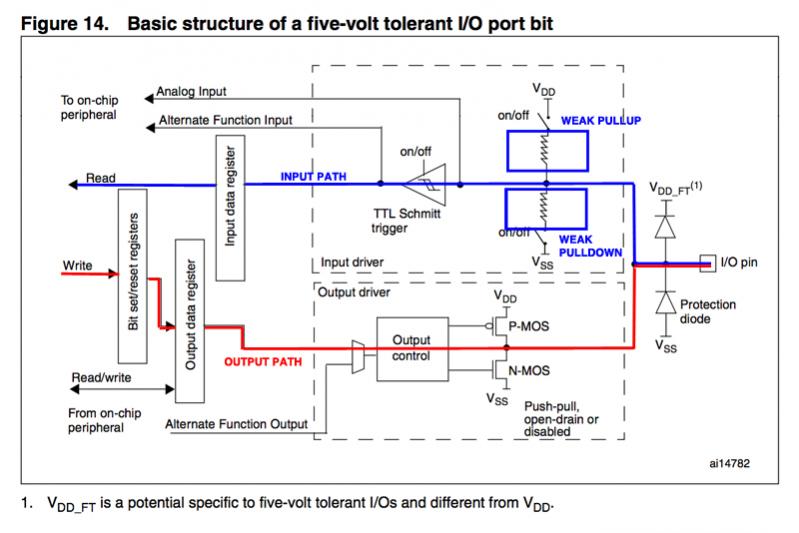
This looks much more complex, I’m showing the path an input signal would take if the port were programmed as an input in blue. The path if programmed as an output port is in red. On the input path I outlined two resistors, a weak pullup and a weak pulldown. These resistors have a switch in series that allow them to be disabled. I won’t say too much more about this schematic, you can ask questions later if necessary.
There are several ways this port (called a GPIO port which means general purpose input/output port) can be programmed by the firmware, a summary of this is shown in the following table.
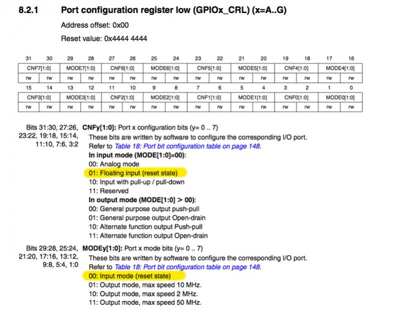
Again this looks complex but the pertinent details are as follows.
There are four different ways the port can be programmed as an input.
- An analog input (not every port can do this)
- A floating input (both pullup and pulldown resistors are turned off)
- An input with the weak pullup enabled.
- An input with the weak pulldown enabled.
When programmed as an output there are also different choices to be made.
- The frequency response, 2MHz, 10MHz or 50MHz. Lower frequencies are chosen to suppress noise and limit slew rate of the edges.
- Push/pull mode or open drain (also known as open collector). This determines if the signal is both driven high and low by turning on transistors or only driven low with the expectation that an external resistor will be used to drive the output high.
- Normal or alternate function. Alternate function mode is selected when the port is used for things like a UART or I2C interface. In this situation the signal comes from that special function block inside the micro-controller rather than the output register.
When the micro-controller is reset, the port is programmed as a floating input, the condition I highlighted in yellow above. This is a safe condition but is not very useful unless the port is dedicated to be an input and a known circuit used to drive it externally. The most typical selection for an input port would be to program it with the weak pullup enabled, this is the situation shown in the cortex user manual above.
The final schematic I want to show as background is the pneumatics driver cable (the cable that goes between the cortex and pneumatics solenoid). Now this schematic is just conceptual, I don’t have any pneumatics at home and have never pulled apart a cable to reverse engineer it, however, it is conceptually correct even though the exact detail may be different.
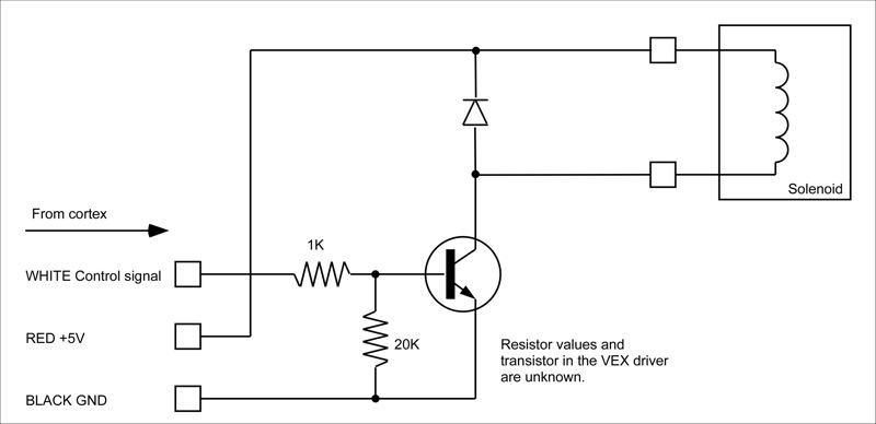
The control signal from the cortex output port drives (perhaps through a series resistor) the base of a transistor (which may be a MOSFET, I don’t know). A logic high turns the transistor on allowing current to flow and energize the external solenoid, a logic low turns the transistor off. Notice that there is a pulldown resistor from the transistor base to ground, this makes sure the transistor is off when there is no control input.
Firmware startup
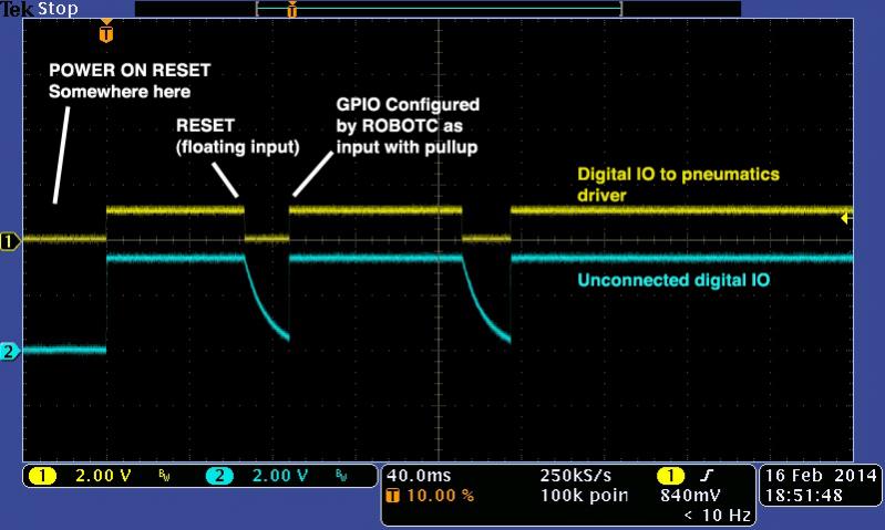
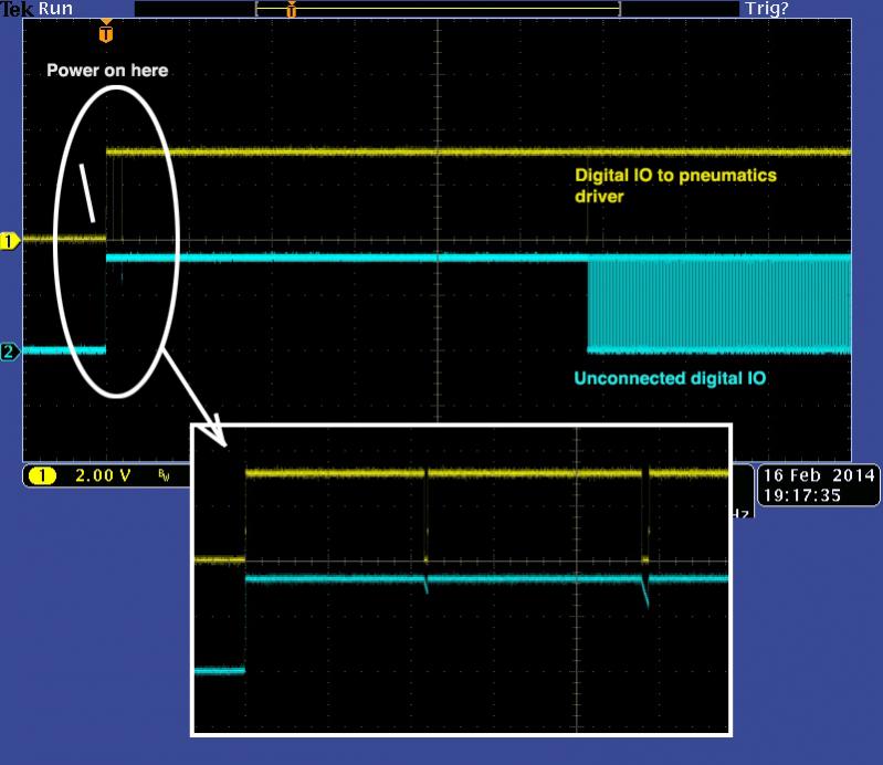
When the firmware on the user processor starts, there are a series of steps performed to configure the digital IO ports. Firmware will nearly always assume that ports are inputs unless specified otherwise, this is because configuring a port as an output and driving into something not designed to be driven is generally a bad idea. Each programming option has slightly different behavior, I will outline what happens for each one below, however, one thing to mention first is that the master processor has control over reset of the user cpu, this is important to remember because it means that often the first part of the firmware reset sequence can happen multiple (usually three) times.
ROBOTC
- processor is reset
- processor has set all GPIO ports as inputs that are floating
- RobotC configures all GPIO as inputs with weak pullups
- wait until master processor communications is established ~ 3 seconds when tethered
- Check for user program and run if found
- Configure GPIO ports to the user program
- If the competition template is used then a 2 second delay
- pre_auton runs
EasyC
- processor is reset
- processor has set all GPIO ports as inputs that are floating
- EasyC configures all GPIO ports to the user program
- wait until master processor communications is established ~ 3 seconds when tethered
- initialize runs
ConVEX
- processor is reset
- processor has set all GPIO ports as inputs that are floating
- ConVEX configures all GPIO ports to the definitions in the board.h file (the default is input with weak pullup)
- vexUserSetup is called, GPIO can be reconfigured to the user program requirements here.
- 2 second delay to match ROBOTC competition template
- vexUserInit runs
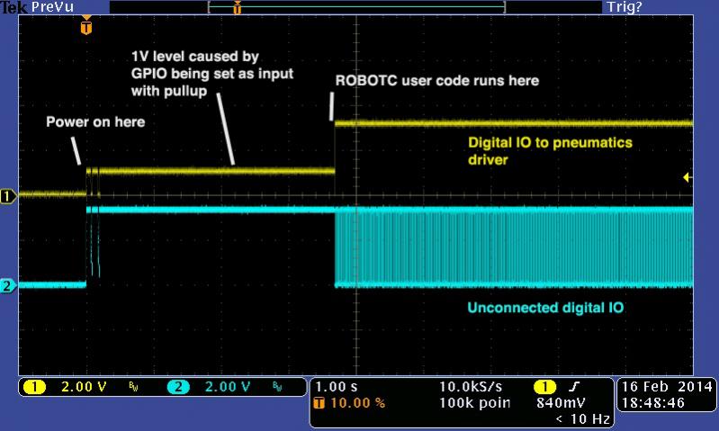
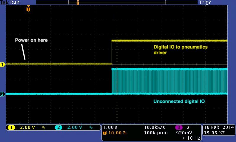
So ignoring ConVEX for now, the big difference between ROBOTC and EasyC is that EasyC leaves all GPIO as floating inputs until reconfigured by the user program. ROBOTC always configures GPIO as inputs with pullup resistors first, the user code will run a few seconds later and reconfigure the ports as outputs if necessary. For a pneumatics port, EasyC starts with the port as a floating input and then changes it to be an output, ROBOTC starts with the port as a floating input, changes it to an input with a pullup and then (later on) changes that port to an output. If reset happens more than once then the first part of this sequence will happen multiple times, my measurements show that in addition to power on reset there are two subsequent master processor initiated reset sequences.
To understand why I’m highlighting the input port configuration we can look at the difference between these when connected to the conceptual solenoid driver.
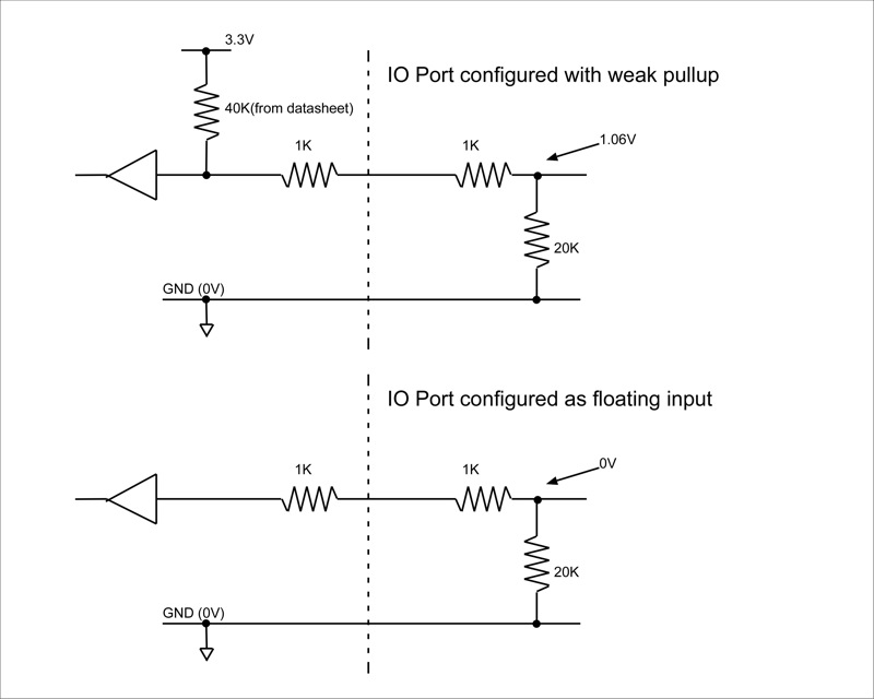
When configured with a weak pullup, we have ~1V (the exact number is unknown) at the base of the transistor. When configured as a floating input we have something close to 0V. The transistor will sometimes turn on when drive with 1V, it will not when at 0V.
This is the root cause of the problem, configuring the GPIO as an input with a pullup can often cause the pneumatic solenoid to activate. ROBOTC will allow this to happen, EasyC does not.
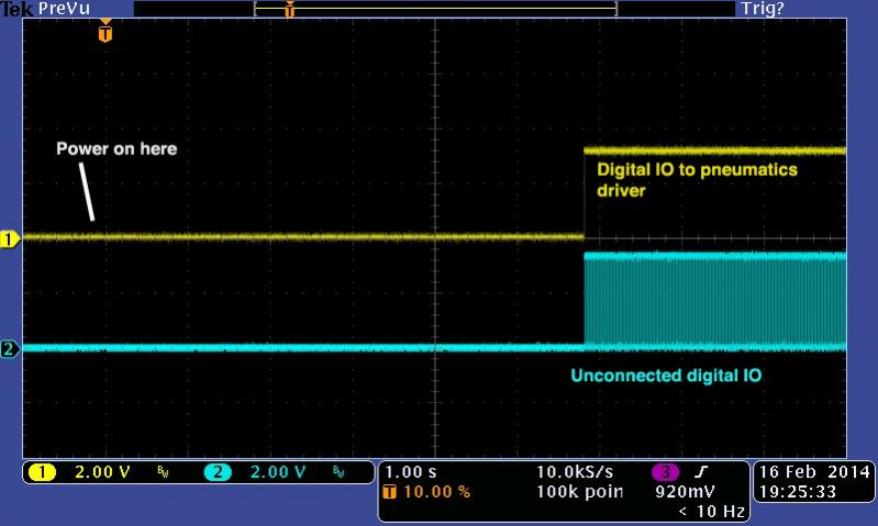
In the next post I will show some examples of this sequence as oscilloscope traces so give me a couple of hours before commenting.