Hello,
I’m not a designing master and I’m sure there are other people out there who could give better advice, but I’ll help in any way I can.
Firstly, the screw joints themselves.
I would like to make start saying I’m still researching screw joints, so I definitely don’t know a ton about them, but I got some decent advice on the G2M forum (giving credit where credit is due, I got a lot of good information from Amanda on that forum). Here’s a link to the thread (if it’s not allowed to share links to 3rd party sources, my dearest apologies, mods): Drive Screw Jointing - #13 by VexTeamZ - general-discussion - The G2M Forum
I would consider adding another nylock nut to essentially “sandwich” your joint. This would help in preventing the screw from getting lose and basically slowly unscrewing as you drive it.
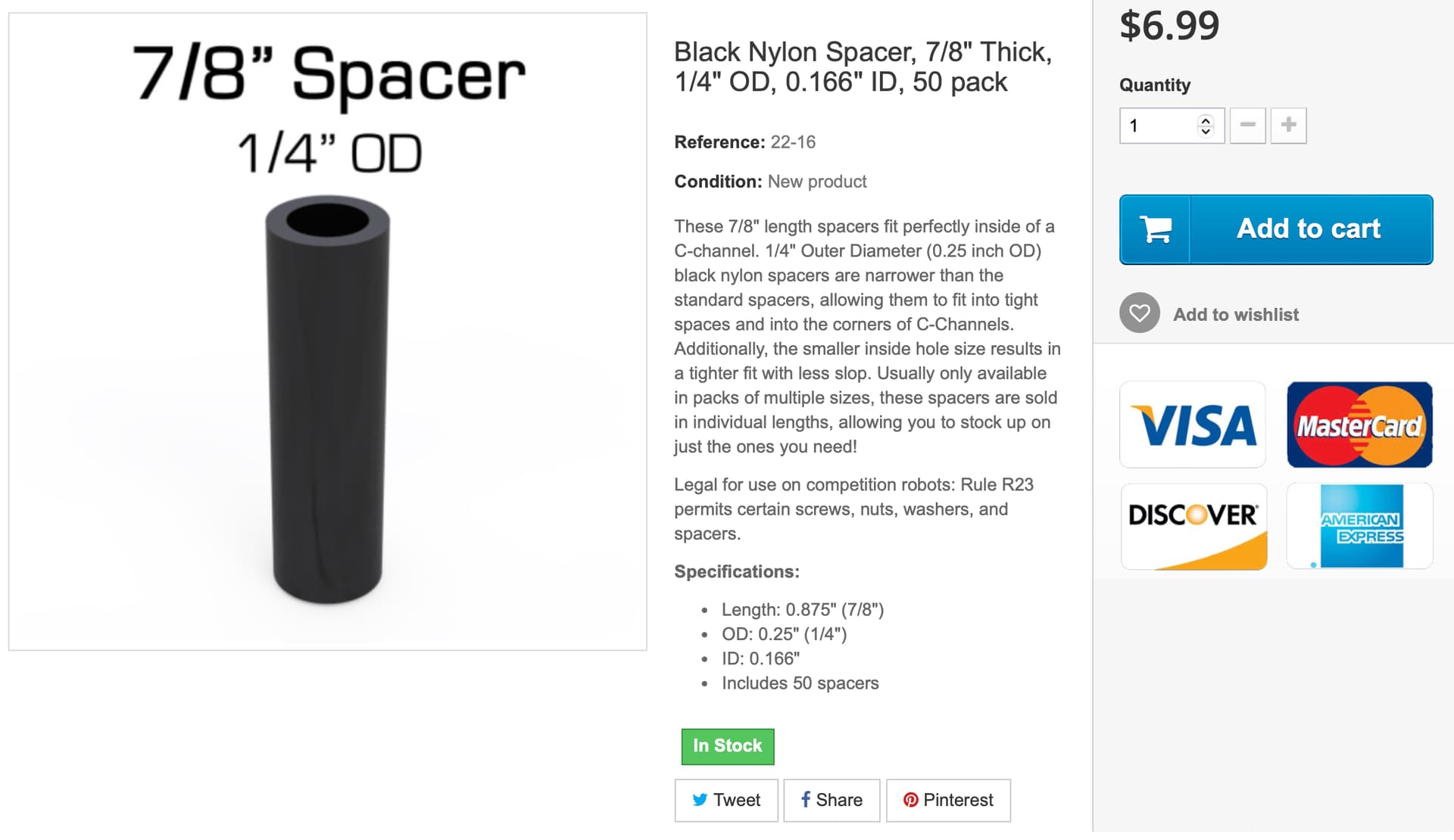
In general, I would just keep experimenting with spacers, washers, etc. until you get a conventional width that is applicable in Vex.
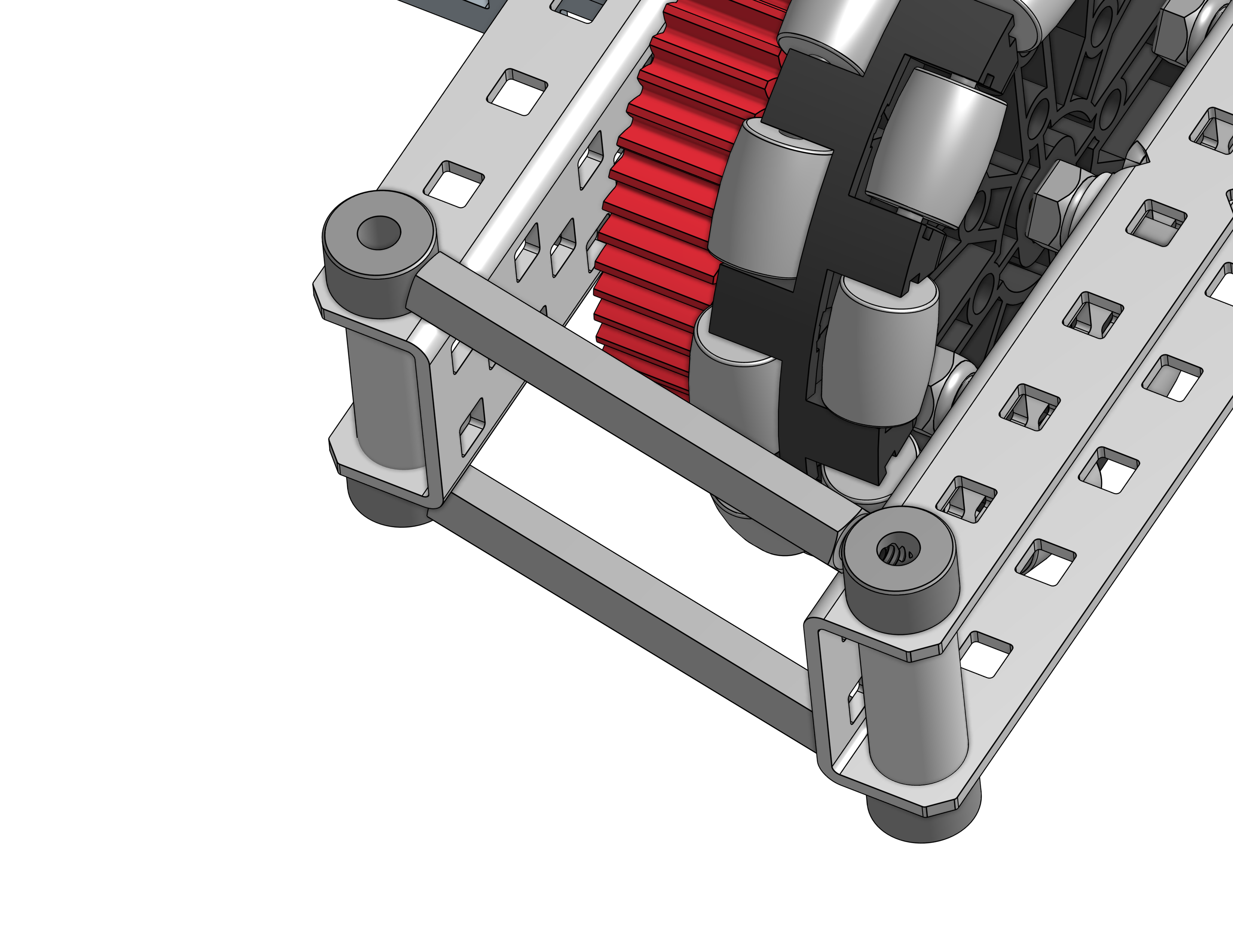
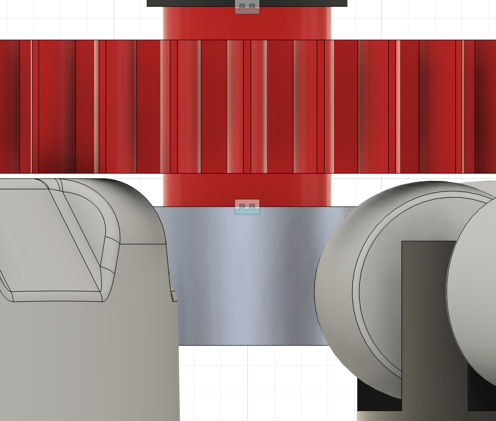
Here is a design that I developed for my team’s drive. Granted, this could be completely wrong and not a viable design (I mean I really am new to them), but I designed it using knowledge from others. (also sorry that the text is hard to see if you’re using dark mode like me–this was made for a lighter background)
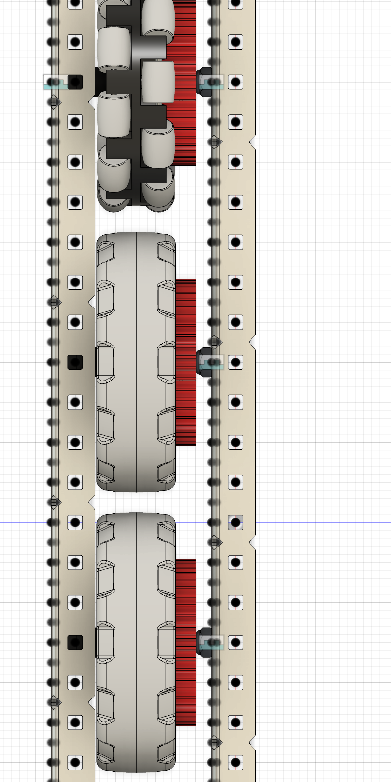
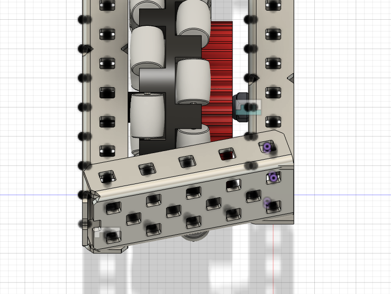
Side view
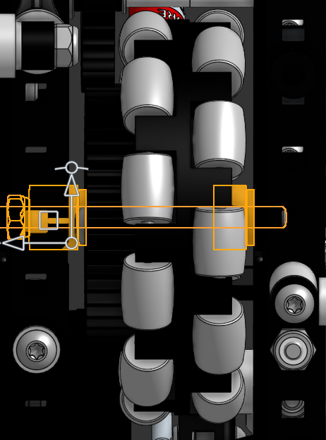
Gear Hidden to show insides
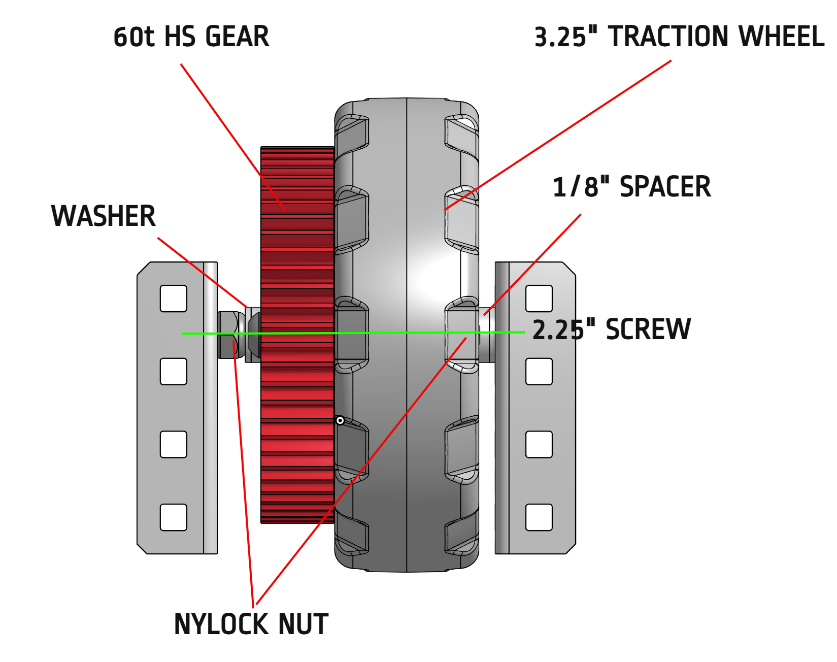
Measurements
(Please do your own designing, this is just an example)
Note that this is a 4 hole wide drive which is not necessarily the most advanced, but I frankly didn’t trust myself making a 3, lol.
I used …
- Nylock nuts (these are typically recommended for screw joints if you didn’t know)
- Spacers to ensure that the joint was rigid and had even less wiggle room
- A standard format for all the axles to ensure that the gears and wheels align as close as possible
Now, time to talk about the drive sandwich caps…
While I have nothing against using the C-channel, it can be rather bulky and hard to screw to the drive sandwich. Perhaps you should consider using standoffs and shaft collars instead (You will need a coupler to connect them when you build them).
Now other people may have their own (and probably better) bits of advice, but there was mine.
Hope this helps.