I use a potentiometer in conjunction with the motor’s internal encoder values. The potentiometer determines the stopping and starting positions, while the internal encoder’s value is mapped to a specific velocity. For example, if the tray is tilting upwards, and the internal encoder value is 400, then the velocity of the tray is 40. You can experiment with different continuous mathematical functions to find an appropriate “mapping” curve. I do this by representing the x value of the function by the internal encoder’s value and the y value by the output velocity.
So why not use the potentiometer to map the velocity of the motor? The potentiometer does not return perfectly linear values. Meaning a rotation from 30 degrees to 60 degrees could change the pot’s value by 150 while a rotation from 60 degrees to 90 degrees on the same pot could result in a change of 120. If the sensor was perfectly linear, then a 30 degree rotation of the sensor would change pot’s value by the same amount. See the jerks in potentiometer value below:
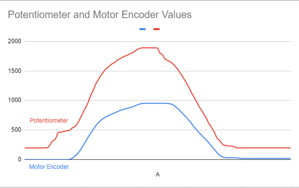
A potentiometer is really just an adjustable electrical resistor, so by turning it you are just changing the voltage that it detects. This method of measurement results in the slight error in the linearity of potentiometers. I tried to use a pot as the input of my mapping function, but as expected there were lots of random spikes due to its non-linearity. Considering you want the tray motor to move as smoothly as possible, using the pot values mapping the motor speeds is not feasible.
Another reason I use both sensors in conjunction is because the pot always measures the absolute position of the system however, the encoder value is only relative to the system’s position at the start of the program.
Understanding how each sensor works, and their strengths / limitations helped me determine the best way to implement each sensor to my advantage.