Back in June I posted a thread about an experiment I had done for controlling the velocity of a flywheel. This experiment was done using code I had written using my ConVEX framework. I subsequently posted a simplified version of the code written in ROBOTC.
I have received some requests to explain this a little more, so here is a slightly more detailed explanation of how the code works.
To start with lets look at a diagram of the system we are trying to implement.
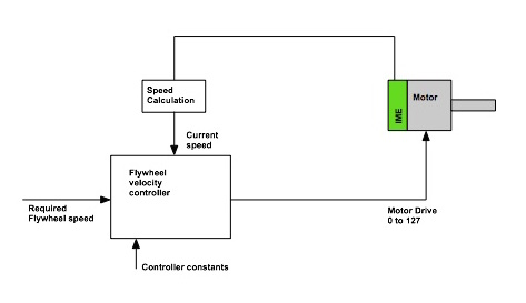
There are one or more motors that are connected to the flywheel. I’m not showing the mechanical components here, for the sake of this discussion it doesn’t matter how many motors there are but the assumption is that they are all mechanically connected together and work as one big power source.
There is a means of measuring how fast the motor is turning. We don’t have much choice for the means of doing this on a VEX competition robot, I prefer to use an IME, a quad encoder could also be used.
The flywheel velocity controller is a software algorithm that compares the measured speed of the flywheel to a target speed and makes adjustment to the motor control to minimize the difference between these two.
My original ROBOTC code uses some programming techniques that beginners may not be familiar with. Specifically it uses a structure to collect all of the related variables together and then a pointer to this structure to pass it to the functions that will use its contents. I rewrote this code to eliminate this structure and use individual global variables instead. This code is posted here.
Lets look at what is going on in this program.
The speed measurement function.
/*-----------------------------------------------------------------------------*/
/** @brief      Calculate the current flywheel motor velocity                  */
/*-----------------------------------------------------------------------------*/
void
FwCalculateSpeed()
{
    int     delta_ms;
    int     delta_enc;

    // Get current encoder value
    encoder_counts = FwMotorEncoderGet();

    // This is just used so we don't need to know how often we are called
    // how many mS since we were last here
    delta_ms = nSysTime - nSysTime_last;
    nSysTime_last = nSysTime;

    // Change in encoder count
    delta_enc = (encoder_counts - encoder_counts_last);

    // save last position
    encoder_counts_last = encoder_counts;

    // Calculate velocity in rpm
    motor_velocity = (1000.0 / delta_ms) * delta_enc * 60.0 / ticks_per_rev;
}
The idea here is to calculate the speed of the flywheel using the number of encoder ticks we count in a certain time interval.
We read the encoder into a variable called encoder_counts, I use a function called FwMotorEncoderGet to get this number, all that function really does is use nMotorEncoder to read the IME attached to one of the motors. We can calculate how many counts the encoder has moved by subtracting the value we read the last time this function was called, this is saved in a variable called delta_enc. We also calculate how much time has elapsed since we last called this function. The ROBOTC function “nSysTime” returns a number that shows how long the cortex has had power. We can use this number, along with the its saved value from the last time the function was called, to determine how many mS have elapsed since we last did the speed calculation.
We calculate the motor speed in revs per minute based on the equation ( change in encoder count / change in time ) which is then converted from encoder_counts per second to motor revs per minute.
for example,
we see a change of 10 encoder counts in 25mS (0.025 seconds) from this we can calculate that there would be a change of 400 counts in one second. We need to know how our motor is geared to then calculate rpm, for a 393 motor with the “speed” gears the wiki tells us there will be 392 counts for one revolution of the motor output. So to convert from ticks/sec to rpm we do the following math. rpm = ticks/sec * 60 / 392, for our example this would be 400 * 60 / 392 = 61 rpm.
The velocity control function
The example code implements the TBH (take back half) algorithm, you could also implement a more traditional PID algorithm in this function block.
/*-----------------------------------------------------------------------------*/
/** @brief      Update the velocity tbh controller variables                   */
/*-----------------------------------------------------------------------------*/
void
FwControlUpdateVelocityTbh()
{
    // calculate error in velocity
    // target_velocity is desired velocity
    // current is measured velocity
    current_error = target_velocity - motor_velocity;

    // Calculate new control value
    drive =  drive + (current_error * gain);

    // Clip to the range 0 - 1.
    // We are only going forwards
    if( drive > 1 )
          drive = 1;
    if( drive < 0 )
          drive = 0;

    // Check for zero crossing
    if( sgn(current_error) != sgn(last_error) ) {
        // First zero crossing after a new set velocity command
        if( first_cross ) {
            // Set drive to the open loop approximation
            drive = drive_approx;
            first_cross = 0;
        }
        else
            drive = 0.5 * ( drive + drive_at_zero );

        // Save this drive value in the "tbh" variable
        drive_at_zero = drive;
    }

    // Save last error
    last_error = current_error;
}
The inputs to this function are the global variables “motor_velocity” (which we calculated above), “target_volocity”, the velocity that we would like the motor to have, and “gain”, a constant that is used to control how aggressive the algorithm is at trying to get the motor to the target velocity. The output from this function is in a global variable called “drive”, this variable has a range of 0 to 1 meaning motor stopped to motor full speed. A flywheel only needs to be controlled in one direction so we make sure that “drive” does not go negative.
A ROBOTC task that ties these two functions together
/*-----------------------------------------------------------------------------*/
/** @brief     Task to control the velocity of the flywheel                    */
/*-----------------------------------------------------------------------------*/
task
FwControlTask()
{
    // Set the gain
    gain = 0.00025;

    // We are using Speed geared motors
    // Set the encoder ticks per revolution
    ticks_per_rev = MOTOR_TPR_393S;

    while(1)
        {
        // Calculate velocity
        FwCalculateSpeed();

        // Do the velocity TBH calculations
        FwControlUpdateVelocityTbh() ;

        // Scale drive into the range the motors need
        motor_drive  = (drive * FW_MAX_POWER) + 0.5;

        // Final Limit of motor values - don't really need this
        if( motor_drive >  127 ) motor_drive =  127;
        if( motor_drive < -127 ) motor_drive = -127;

        // and finally set the motor control value
        FwMotorSet( motor_drive );

        // Run at somewhere between 20 and 50mS
        wait1Msec( FW_LOOP_SPEED );
        }
}
This function connects the speed calculation to the velocity controller. We have a while loops that does the calculations and then delays for a small period of time (defined by FW_LOOP_SPEED). The loop calculates motor speed, determines what control value needs to be sent to the motor, scales that up to the 0 to 127 values that VEX motors needs and then send it out to them.
Part 2 in the next post