Harvard-Westlake Robotics: AMOGO x DOGO Reveal

In your setup, the standoff is tightened to the locknut. I find this to be the best way to do screwjoints. We are using this method on some of the idler gears in the drive, seen below.

A locknut couldn’t fit in this assembly between the wheel and standoff without using a screw longer then 2". Even though 2.5" screws are legal now, we didn’t want to force teams who are referencing this robot to buy longer then 2" screws, as VEX doesn’t sell them yet.

The exposed screw in the image below is all of the space available, and wasn’t enough for a locknut.

If the standoff is sufficiently tightened to the outer channel then this shouldn’t come loose, but a little bit of purple loctite never hurts.

If the standoff isn’t tightened enough to the outer channel, the standoff could tighten itself to the wheel and jam the drive.

Thanks, I know my team had issues finding the right spacing with the standoff joints because it changed depending on how much it was tightened, an extra turn might mean a washer. I am assuming this is a common problem that just needs to be practiced a lot.

Yeah, I usually place my outer channel on and see how all the standoffs align and tune all of them until the locknuts are in the right place. After this first tuning, you shouldn’t need to mess with the locknut placement again. Could also put temporary standoffs in the drive and adjust the locknuts until everything contacts, then remove those standoffs.

First, great robot and cad… amazing work…. About the above, I have a question, it seems you are using a “normal/thin gears” that do not have spaces for a green insert, it comes fixed with a square hole… how do you attached the screw? Drill?

They were drilled with a #19 drill bit that can be found here from McMaster Carr.

What is the back piece attached to the drive train? It’s probably pretty obvious but I have no clue what its intended purpose is.

If you are talking about AMOGO, I believe that angled piece is used to be able to climb up the platforms. It lowers a side of it down so that the wheels can reach it.

Example would be in the first scrimmage they posted, around 1:48.

Oh yeah that seems very obvious now, I just didn’t see it or didn’t pay enough attention to it during the reveal video. Thank you very much

First of all, would like to highlight that this robot is amazing!
Slightly confused here however: on the CAD for the AMOGO drive train, how do the wheels turn? Don’t keps nuts keep the screw tightened against the C-Channel? Or do we have to assemble it a special way?
What makes this assembly better than the usual drive train assembly with shafts?

Yes the keeps nut does keep the screw firmly attached to the C-Channel. This is what they want to happen. it is used to create a fixed axle that is very conveniently a circle. This means less friction, which is good very good. Because friction is bad, very bad (for moving parts (most of the time))

The screw is being used as a fixed axle that is effectively part of the C-Channel. The wheel has circle inserts so that it spins freely and is powered because it has been screwed to the sprocket.

Welcome to the community!

Thank you!

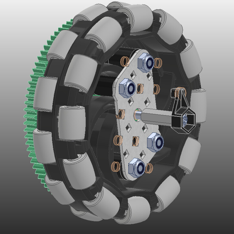
These are called screw joints. The keps nut is tightened to the inner channel, and the standoff is tightened to the outer channel. If the space between the keps nut and standoff is greater then your wheel assembly, it’ll be low friction and free spin. If your keps nut / standoff are tight, then nothing should come loose.

When building a drive, if you just screw the drive pontoons (“pontoon” refers to the inner and outer drive channel as an assembly) to your cross brace, you’ll find that the drive pontoons don’t want to stay square. This is because screws don’t fit perfectly in the square holes of c-channels. This can be mitigated by using shoulder screws, but doesn’t entirely fix it. (it’s good practice to use shoulder screws though)

Having something that ensures the distance between the inner and outer drive channel is the same all the way across is essential for your drive to have low friction. If they aren’t, then anything you build on top of that risks not being square and your drive axels increase in friction or will struggle to drive straight.

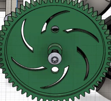
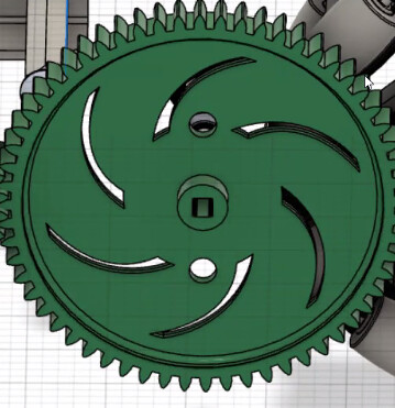
Usually this is done by having standoffs that go between the inner and outer channel, but when you run gears all the way along the drive you lose a lot of holes to put standoffs. By using this style of screw joint for the wheels and unpowered idler gears, the joints are keeping the inner and outer drive square.


When putting standoffs inside of drive pontoons, the spacing is never a clean standoff size. It’s always a size down standoff from what almost fits, a spacer and some washers. This changes a bit if you’re using steel or aluminum, mixing both, or the direction of your drive channels, so be sure to check CAD for your setup to get as close as you can to the correct spacing.

Before I mount the outer channel, I tighten all my long screws to the inner channel. I’ll make one wheel assembly with some spacing, put the standoff on loose, then attach my outer channel. At this point, only 1 wheel is mounted, and I see if everything lines up and if my spacing is correct (it never is first try). After the spacing is good, I’ll mount all of my wheels.

When tightening the standoff, it’s important to tighten it to the outer channel, using pliers or a wrenchy wrench. If you don’t, it’ll tighten to the wheel stop it from spinning. A bit of purple Loctite on the screw between the outer channel and standoff will help make sure that screw doesn’t come loose and is still removable for drive maintenance.

The keps nut on the inside shouldn’t come loose if tightened enough, but this can be replaced with a locknut (normal or thin) and then definitely won’t come loose.

First of all, I’d just like to say that your robot designs and code are amazing! Great job one this, and thanks a lot for the resources you provide the community

While building the chassis, while we were building it according to the design, we ran into an issue. It told us to run a circle screw through a square insert.

This is the link to the screenshot that we saw in Autodesk
image

My team is quite confused about this. Can you help out?

This is the picture of the square insert on the gear

image

The gear is drilled out in the center to allow it to spin on the screw. It was omitted from the cad design since in most cases it wouldn’t be seen.

Hello again!
So, I’ve been looking at both of these designs, and I’ve become quite intruiged. I’ve been thinking about if and how I could possibly combine the two designs in some way, making a more affective AMOGO, or a more ring-focused DOGO somehow.
As I researched into this, I found that the “side mogo” component in the cad design that you posted simply acts as a arm to help manipulate the mobile goals. I was wondering why you hadn’t done that to both sides of the robot?
Would that make it out of size? Or would it interfere with other parts?

My guess is just because they ran out of motors.

Well, I’ve been counting the motors for each of the components, and I only count seven. So, I don’t think that’s the issue. I think that the issue could be the size, as well as the fact that it would be in the place that the brain is in. So, just asking, are there any other viable locations for the battery?

Amogo runs 2 motor conveyor. I believe the motor distribution is this: 4 motor drive, 2 motor intake/conveyor, 1 motor lift, and one motor grabber.

Hello!

The electronics can go anywhere that doesn’t interfere with any of the lifts or ring mechanism.

AMOGO is an 8 motor robot, with 4 drive, 2 for rings, and 2 for mobile goals.
DOGO is a 7 motor robot, with 4 drive, and 3 for mobile goals.

Neither robot has pneumatics, motors could be removed from some lifts and converted to pneumatic lifts.

If you had three mobile goals in the robot, two on the sides and one in the front, where the ones on the side are similar to AMOGO, you cannot platform because one of the side goals would hit the field perimeter.

Maybe this could be fixed by raising the goal above the height of the field perimeter?

What are the cartridges in the motors for DOGO? I have made 2 different designs for lifts, and both had to have super high torque.