I have been using Inventor for about a year now, and it has been very useful in allowing me to create a number of different components for my team’s competition robot. However, I have been having trouble figuring out how to put high strength chain links together and how to put those over high strength sprockets. Any help would be greatly appreciated.
Same as you would connect any other part together, you use the Constrain tool. Simply make a few constraints, that cause the one end of one chain link connect to the opposite end on the other. Then once you have a long enough chain, you can make more constraints to make the chain wrap around the sprockets.
Hope this helps. I could post pictures, if you’d like.
~Jordan
It would be great if you could post pictures because I have tried that method before but without success. I couldn’t find any two points to constrain the links together well.
Alright, I shouldn’t be too busy a little later today – I’ll post some pictures and explain them in a few hours.
~Jordan
First off sorry for the late reply – I’m bad at guessing, and my memory is horrible. Anyways onto this tutorial:
[ATTACH]3976[/ATTACH]
- Open up your Assembly, and Import your High Strength Sprocket (size of your choice, I’m using the 18-Tooth Sprocket for this demonstration) as well as your High Strength Chain Link. (as shown in the picture above)
[ATTACH]3979[/ATTACH]
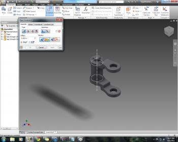
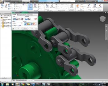
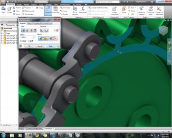
2. Click the Constrain Tool. This tool will be very useful for building robots in Autodesk Inventor, so you should get familiar with it if you aren’t already. Once the Constrain tool window pops up, the first thing you want to click on will be the axis shown (in white) in the picture above, on your High Strength Chain Link.
[ATTACH]3982[/ATTACH]
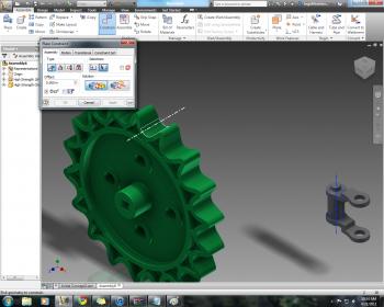
3. Click on will be the axis shown (in white) in the picture above, on your High Strength Sprocket.
[ATTACH]3985[/ATTACH]
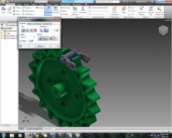
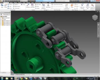
4. Click the “Apply” button on the Constrain tool window, and your High Strength Chain Link should be mated to your High Strength Sprocket, just like it is in the picture above.
[ATTACH]3988[/ATTACH]
5. Simply repeat steps 1-4 for all your Chain Links.
(Continued on the next post.)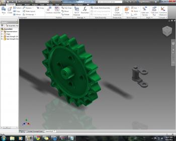

[ATTACH]3991[/ATTACH]
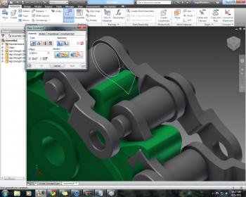
6. Notice that the Chain Links are mated to the Sprocket, but are not yet connected to each other. To do this, start by clicking the axis shown (in white) in the picture above, on the first High Strength Chain Link.
[ATTACH]3994[/ATTACH]
7. Click the axis shown (in white) in the picture above, on the next High Strength Chain Link.
[ATTACH]3997[/ATTACH]
8. Click the “Apply” button on the Constrain tool window, and your High Strength Chain Links should be connected.
[ATTACH]4000[/ATTACH]
9. Now, you may realize that the Chain Links in this image look quite off, and not centered on the Sprocket like they should be. (The model you are working on probably looks much the same.) This can be fixed quite easily, and I’ll explain that in the next step. For now repeat steps 6-8 for the remainder of your Chain Links.
[ATTACH]4003[/ATTACH]
10. Click the face shown (in white) in the picture above, on your first High Strength Chain Link.
(Continued on the next post.)

[ATTACH]4006[/ATTACH]
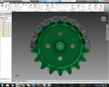
11. Spin around to look at the other side of your High Strength Sprocket, and click the face shown (in white) in the picture above, on your High Strength Sprocket.
[ATTACH]4009[/ATTACH]
12. Before you click “Apply”, Change the “Offset” to “0.008 in”. This number is a good centering offset amount. Now you may click the “Apply” button on the Constrain tool window.
[ATTACH]4012[/ATTACH]
13. Repeat steps 10-12 for the rest of your High Strength Chain Links.
[ATTACH]4015[/ATTACH]
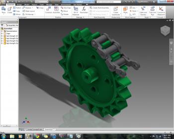
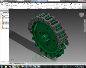
When you are finished, your model will probably look something like the pictures above and below, with the Chain Links mated and connected around the Sprocket.
[ATTACH]4018[/ATTACH]
Once you have finished this, it should be straightforward as to how you will connect chain together to reach your other Sprocket, and wrap it around that one, making the chain come back around to create your end Chain/Sprocket assembly.
Feel free to ask more questions, and I hope this helped.
~Jordan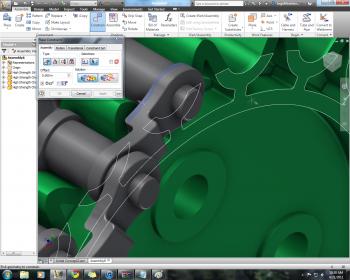
That is helpful for all teams, that basic technique could really help. Thanks for the tutorial.
No problem! And I do hope that other teams/people find it helpful.
~Jordan
Does anyone know how to connect chain so that it can be animated? The only way I’ve found is to use the sprocket generator (I think that’s what it’s called… I don’t have Inventor open right now).
That’s the only way that I have found, as well. I don’t believe there is a way to use your own sprockets and chain.
~Jordan
I want to do the same thing, except with tank tread links, and for that i cant use the sprocket generator, so is there any other way to do it? i want to be able to animate it.
thanks
– monkeyboy
As far as I know, it is possible, but difficult.
In the past when I’ve tried, I’ve started by constraining the two sprockets as you would with gears, but turning in the same direction, with the appropriate ratio. Ive then managed to create a separate part which I used as the path I wanted the individual links to follow and constrained them with coincident and (reversed) flush constraints.
After that point, I got stuck on how to make the sprockets and links move in time…
Alternatively, I havn’t used the sprocket generator much myself, but… could you create the chain using the generator, and them constrain VEX links/track to the generated links, then hide them so only the VEX ones were visible?
I will try to have a look at it myself again in the next couple of days if I get the chance…
I am trying to setup Vex chains for an animated demonstration of a simple chain lift.
I have been unable to make the roller chain tool work with Vex chains.
I made a chain by constraining (mates & flushes) individual links together. I extruded a surface with the profile of the path that the chain will follow as a “chain guide”. Then I used the transitional constraint to stick the chain to the surface. Everything works with small numbers of chain links.
When I added all 212 chain links with five constraints each, Inventor stopped working properly. Everything slowed down (I’m using a laptop with an i5 processor and 1GB of video RAM that I bought for CAD) and Inventor crashes frequently.
I need a more efficient way to make this work. Has anyone made this work? Any ideas?
I found a post about a tutorial online where someone does what I want to do, just better.
Thanks for that, Josh! ![]()
~Jordan
I tested it last night with Vex chain and the geometry that I needed and it worked. I have an animated vex chain with 212 links.
While searching for how to do this myself, I stumbled upon this video. This should help a lot. http://www.youtube.com/watch?v=DiBGYdbBPHo . Basically, you create a sketch of the path of the chain and create a pattern. You use that sketch to place the chain and use the pattern created to duplicate it. Probably would be easier to just watch the video. ![]()
I created a video tutorial to show how to create VEX chain or tread on sprockets in Inventor. I did not get as far as animating it yet, but it is good for basic visualization.
The procedure is based on the video linked elsewhere in this thread, but it is specific for VEX.
