Wdym by same extent?
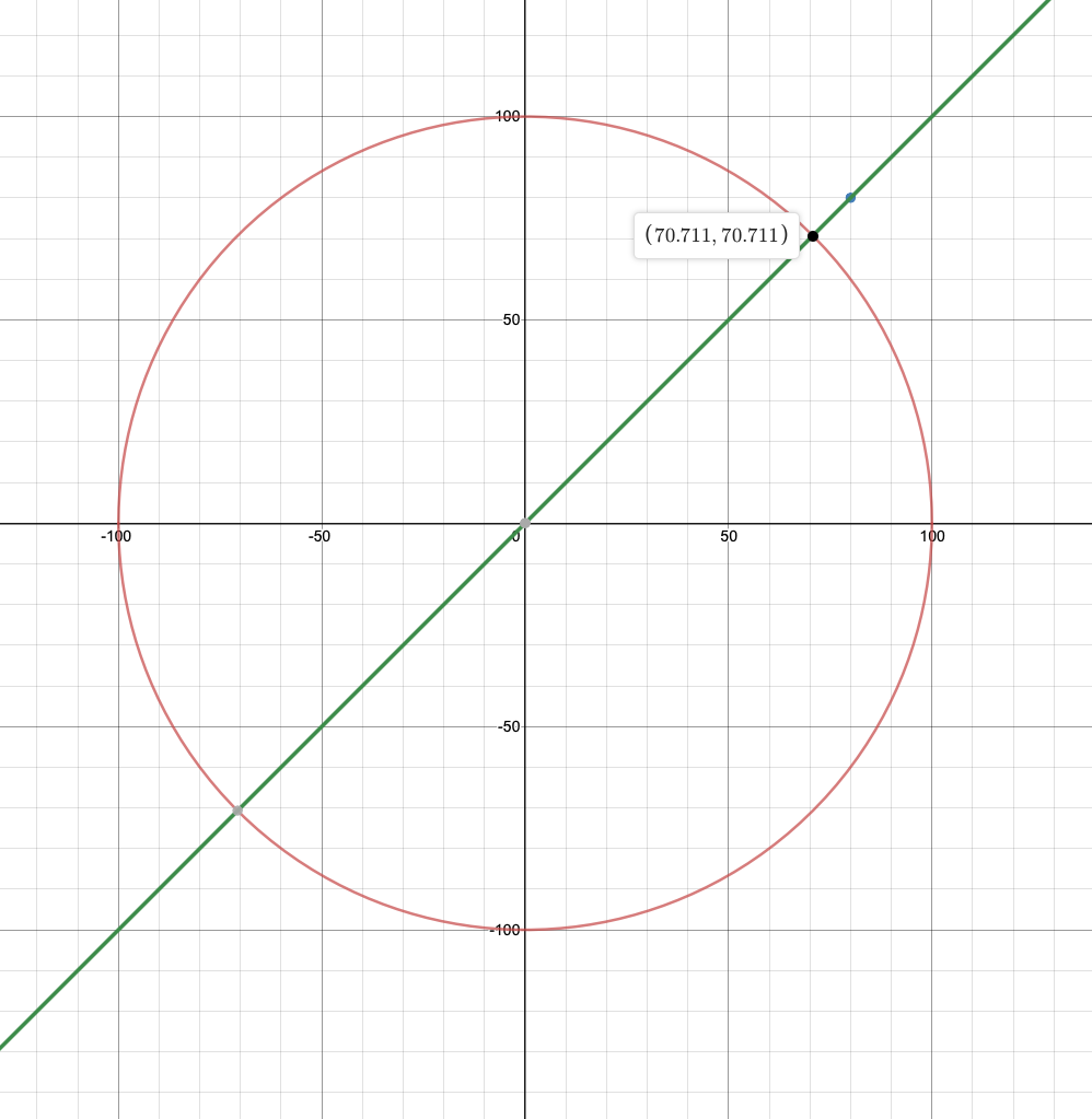
I have been looking mainly at the first quadrant for understanding this problem
It is a perfectly reasonable thing to expect the joysticks to output 100% on both axis when the joystick is moved all the way to 45 degrees (and all the other corners). After all, you want to be able to move as fast as you can.
As stated in this thread, this can be normal behavior, as you are trying to fit a circle into a square. However, I had hoped VEX had mitigated this on the new V5 controllers, but had never tested. I guess they don’t.
I would imagine not being able to turn and drive at full power being a pretty significant efficiency loss, which is why my team has always used 2-stick arcade control. However, with a holonomic drive you need to use both axis on one joystick.
Here is something interesting about X drive control. Since you are already at a power and speed loss when moving diagonally (as you are only using two motors), if you need to move a joystick diagonally to move the bot diagonally, then those motors could only receive ~70% power, which makes moving diagonally on an X drive even slower.
The solution to this problem is to remap the joystick range into a fish-eye of sorts, stretch the circle into a square. This is a great project, I challenge yall to give it a shot 
This helps a little
THANKS
What you should be seeing is a truncated circle, running a small piece of code like this.
vex::brain       Brain;
vex::controller  c1;

int main() {
    int count = 0;

    while(1) {
        Brain.Screen.printAt( 10, 50, "Hello V5 %d", count++ );
        printf("%d %d\n", c1.Axis3.position(), c1.Axis4.position() );
        // Allow other tasks to run
        this_thread::sleep_for(50);
    }
}
gives data that can be easily plotted, here is the result from a controller I have.
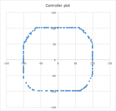
So why isn’t it a circle?
Shouldn’t it be a circle, given that the joystick’s range is, in fact, in the shape of a circle?
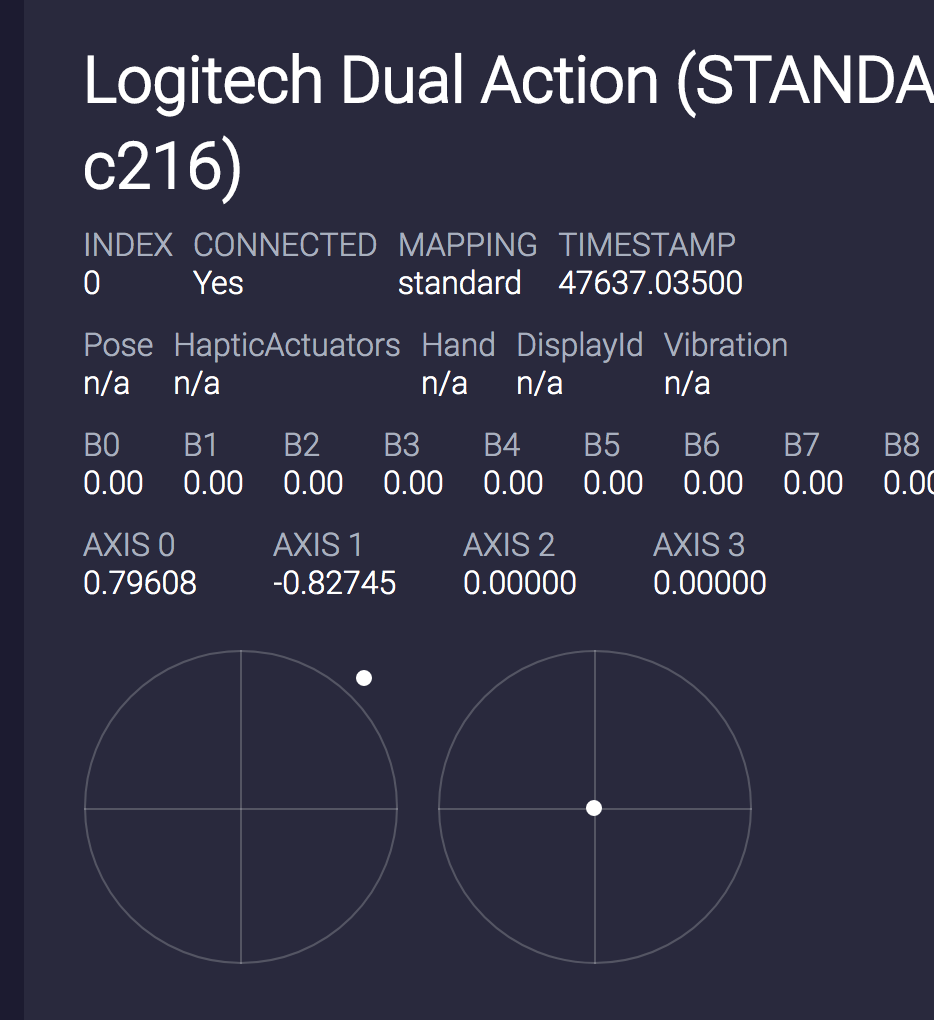
Sounds to me like the potentiometers hit their maximum value before the stick reaches the end of its freedom of movement. This would cause the shape that jpearman posted. A simple test would be to graph the position of the stick in an axis vs the value of that axis and see if the value plateaus before the end of the stick’s movement.
You could physically take a holonomic drive, then try to move diagonally and see if you actually get 70% of your supposed power.
I would try measuring the approximate speed using d/t. time an x drive moving forward for 2 meters, and calculate the speed in m/s. then multiply this speed by .41 to accommodate for the extra speed that x drives give going forward.
now do the same test, this time driving diagonally for 2 meters, and find the speed in m/s.
one of these speeds might be roughly 70% of the other, unless jpearman’s graph is correct, (I assume it is) which would mean that the v5 controller does do a decent job of accommodating for the 70% loss of potential power. (a full square on jpearman’s graph to my knowlege would mean that the v5 joystick does in fact fully accommodate for this potential 70% loss of power. But his graph shows a sort of half-circle-half-square, which means the controller doesn’t fully accommodate for this loss. it still does a better job than just a regular circle, however, like the real joystick would suggest. You can see this in the graph of the Logitech F310, where the dot is out of the circle, but not fully in the corner of the “invisible” square.)
my guess would be that the diagonal speed of the x drive would be roughly 80-85% of the forward speed (minus the .41% speed increase).
No need to have a real drivetrain or sample velocity - just measure the output voltage that is theoretically sent to the motors after calculations done on the joystick values. Besides, measuring distance without odom is tricky if you don’t perfectly move on a diagonal.
My guess, from jpearman’s plot, is the two X-drive motors will receive 80-90 percent power when moving diagonally. That coupled with the loss the power from using two motors and the loss of the x-drive speed advantage results in very slow diagonal movement.
I don’t think so. When you calibrate the joystick - the dot moves around the edge of the circle as you would expect.
It must be clipped later before you get the value in your program.
that’s the calibration ui. That means nothing for the actual calibrated numbers
True, I just meant it would be a fun challenge,
and having a real drivetrain would likely be the simplest way to do it. also by no means would my trial be accurate. But it would be cool if you got somewhere close to 80-90%
Yep. Though I was referring to the range remapping to get an output of 100% on the diagonals as the fun project, you are right that getting experimental results from the bot will help to paint the picture on how much of a problem this is.
I get what we’re discussing here ( a way to map they joystick values to approximate a square rather than a truncated circle). However, the example given here involves X-Drive control, which is not a great example, as it is typically coded such that inputting a value of 70% and 70% causes an output of 140% on the two wheels which should move. (i.e. There’s no need to adjust the joysticks in their current form to control an X-Drive most efficiently.)
Most video game controllers use similar structure to the V5 controller - for example, an Xbox360 controller.
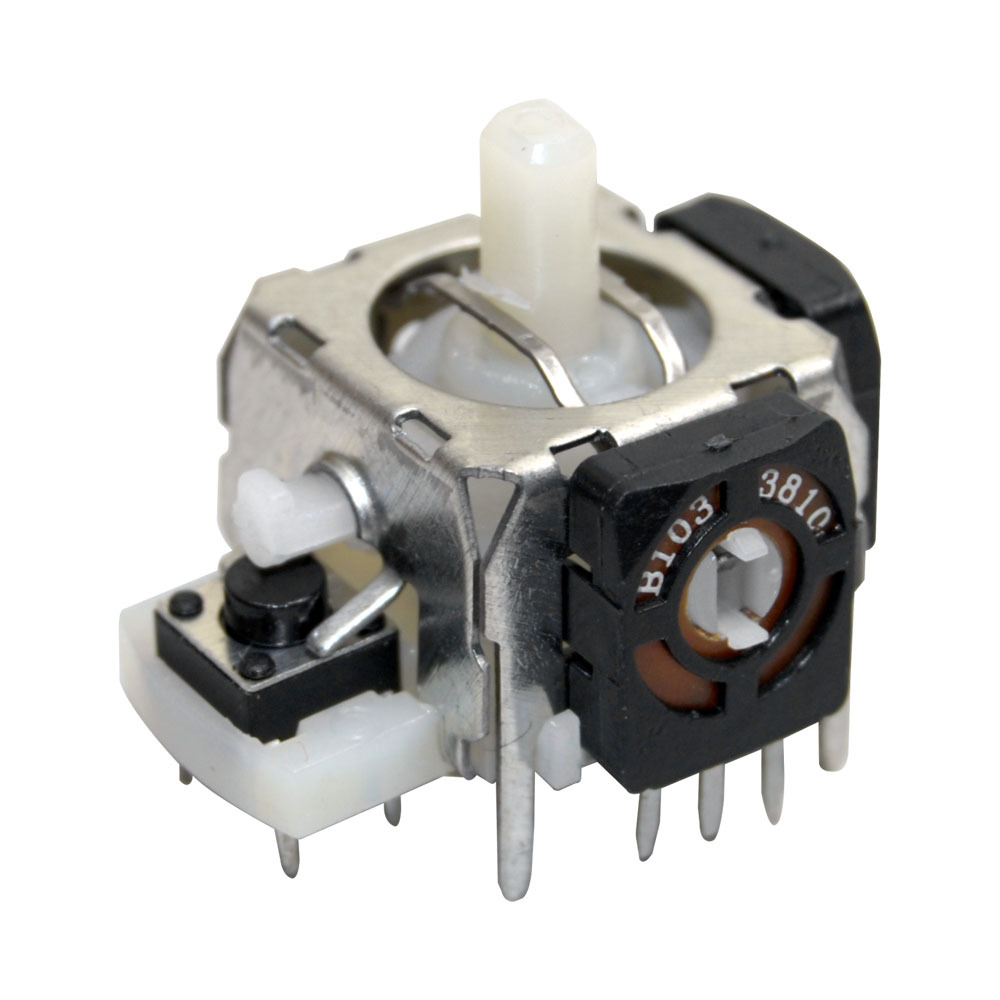
The physical limits of the dual potentiometer joystick are different at the X and Y extremes as opposed to the 45 degree corners. Some of this can be masked away in software (i.e. not using the full range of the potentiometer) to avoid reporting the potentiometer extremes to give the user the perception of a “square” input.