Not all motor ports are created equal

Last September I posted some information on the optimum update interval for motors in this thread. At that time I had been concentrating on the pwm motor ports 2 through 9 but it always bothered me that ports 1 and 10 (being 2 wire ports) may be different. Part of my analysis was based on the fact that the user processor sends the motor speed information to the master processor over an SPI interface once every 15mS. Having dug into this a little more that is not the case for motors 1 and 10, they are in fact controlled by the user processor and therefore do not experience the same communications delay as the other 8.

Timer 4 (2 channels for each motor) of the user processor (this is not the same timer available to ROBOTC or EasyC code) is used to set the pwm control of the two H-Bridge circuits and runs at about 1200Hz. Doing some tests in ROBOTC shows that the motor speed may easily be changed at 2mS intervals, much quicker than the other motor channels. So what does this mean in practice? Well theoretically a PID controller will work much better for these two motors as the PID loop update rate can be faster. Whether this makes any difference with real motors remains to be seen.

1 Like

Interesting. I will keep that in mind for the future. Although as you said, it may or may not make any real difference when applied. Thanks for the information either way though :slight_smile:

I don’t quite understand what the end result of your other post was.
So the minimum loop time for a PID loop to actually change motor values is 15ms? How long does a loop take to actually loop through in RobotC? I’ve heard that it’s about 15ms, but in practice it seems to be much less (I was playing around with the I summing up).

If I’m understanding you correctly, then motor ports 1 and 10 are constantly updated (the value is constantly being sent to the ports)?

The results of the other post:

  • Cortex ports 2-9 have PWM signal with 18ms period. (Yellow line)
  • User processor SPI message to Supervisor updates at 15ms period. (Blue line)
  • Based on these numbers, there are 6 SPI updates during 5 PWM updates.
  • User vex program updates can come at any time.
    – Best case response might be < 2ms.
    – Worst case response might be 18ms +15ms = 33ms
    – The only control you have is how often to update the value that is sent by SPI every 15ms.
    – The SPI is set at 15ms, so each 18ms motor cycle update is sure to have a new SPI value since the last update.
    – In the same way, if you make a SetMotor() update cycle at 12ms, the SPI will always have a new value since the last update.
    – No matter what you do, the response lag will be at the worst case value of 28-33ms, about 1/6th of the time.

If you had a way to synchronize your updates to the SPI updates, you could request updates just before the SPI pulse to the Supervisor. All that does is to minimize the impact that updates have on other tasks.

My understanding is that the DC motor output is also a PWM signal running at ~100Hz = 10ms period, so that may also add some delay. The circuit in the motor that converts PWM control to +/-DC PWM may also add some delay.

Outstanding questions:

  1. What does oscope show for ports 1,10 if there are rapid (4ms period) updates between -127 and +127? 1ms high, 3ms low, 2ms high, 2ms low?
  2. Is the motor speed controlled by the PWM high time, and not PWM duty cycle?
  3. What does the oscope show for the output of MC#29 controller for 33%, 66%, 100% forward values? 33% high, 66% high, 100% high PWM?

Using a task that updates motor values 2-9 once every 10ms fits nicely into the SPA (Sense Plan Act) concept. As I understand it, this task would be the Act portion. This also puts all the motor control in one place, which makes it handy to implement additional features such as

  • estop, and estop when lose wifi
  • filter motor commands for slew rate

Motor values 1,10 could usefully be updated every 3ms, if it makes any difference to some PID routine.

1 Like

Yes, this is correct.

There are two asynchronous events happening.

The SPI communication from the user processor to the master processor which runs every 15mS.
The RC servo control pulse that happens every 18mS.

Worst case would be 15 + 18 + software delay of 1-2mS so perhaps 35mS
Best case if the planets align is perhaps 2mS.

Here are some more examples and tests.

Case 1 used the following code

#pragma config(UART_Usage, UART1, VEX_2x16_LCD, baudRate19200, IOPins, None, None)
#pragma config(Sensor, dgtl1,  outputA,        sensorDigitalOut)
#pragma config(Motor,  port3,           motorB,        tmotorVex269, openLoop)
#pragma config(Motor,  port10,          motorA,        tmotorVex269, openLoop)
//*!!Code automatically generated by 'ROBOTC' configuration wizard               !!*//

task main()
{
    while(1) {
        // run motors forward
        SensorValue outputA ] = 0;
        motor motorA ] = 127;
        motor motorB ] = 127;
        wait1Msec(40);
        
        // run motors backwards
        SensorValue outputA ] = 1;
        motor motorA ] = -127;
        motor motorB ] = -127;
        wait1Msec(40);
        }
}

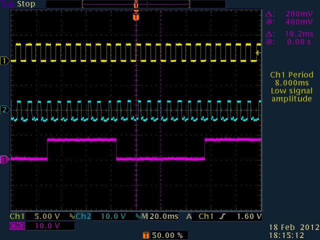
Two motors, one on port 10 the other on port 3 are switched between full forward and full reverse speeds. A digital output is set to indicate which speed has been sent to the motors. The scope trace below shows the resultant motor drive signal on one side of the motor, the blue trace (ch2) is for the motor on port 10, the purple trace (ch3) is for the motor on port3 but is measured after the motor controller 29. The Yellow trace is the digital output and is used to trigger the scope.

TEK00010.jpg

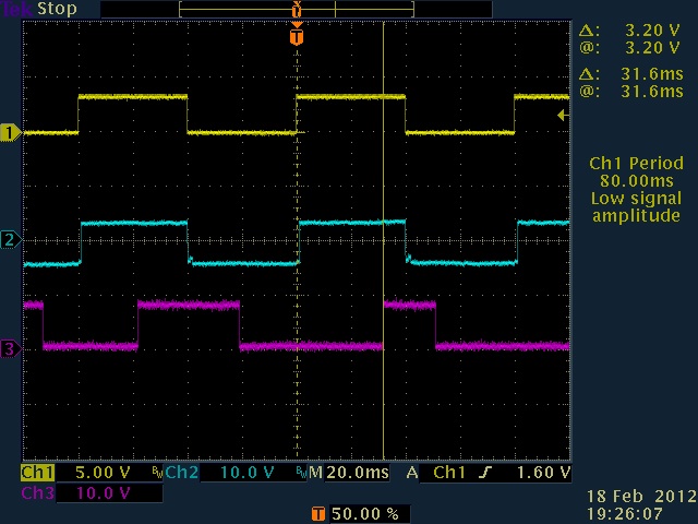
It can be seen that the port 10 motor responds to the speed control almost instantaneously but the port 3 motor has a variable delay between the requested speed to the resultant change in speed. At the trigger point the delay was measured as 31.6mS, however, this is just one example and varies as predicted in my other post.

This trace shows the delay from speed request to the motor 10 output with an expanded timebase.

TEK00011.jpg

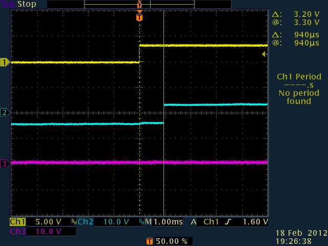
The delay is typically around 1mS and is probably due to the ROBOTC task management.

The next trace was captured using the following modified code.

#pragma config(UART_Usage, UART1, VEX_2x16_LCD, baudRate19200, IOPins, None, None)
#pragma config(Sensor, dgtl1,  outputA,        sensorDigitalOut)
#pragma config(Motor,  port3,           motorB,        tmotorVex269, openLoop)
#pragma config(Motor,  port10,          motorA,        tmotorVex269, openLoop)
//*!!Code automatically generated by 'ROBOTC' configuration wizard               !!*//

task main()
{
    while(1) {
        // run motors forward
        SensorValue outputA ] = 0;
        motor motorA ] = 127;
        motor motorB ] = 127;
        wait1Msec(4);
        
        // run motors backwards
        SensorValue outputA ] = 1;
        motor motorA ] = -127;
        motor motorB ] = -127;
        wait1Msec(4);
        }
}

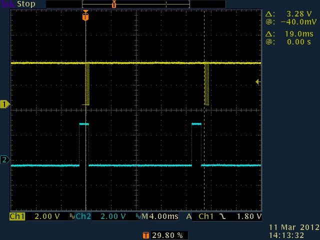
The difference is that the delay between requesting motor speed changes has been reduced from 40mS to 4mS.

TEK00012.jpg

It can be seen that the motor on port 10 is able to keep up with this increase in changing requested speed, however, the motor on port 3 is not able to and changes randomly depending on the relationship between the motor speed request and the SPI message being transmitted to the master cpu.

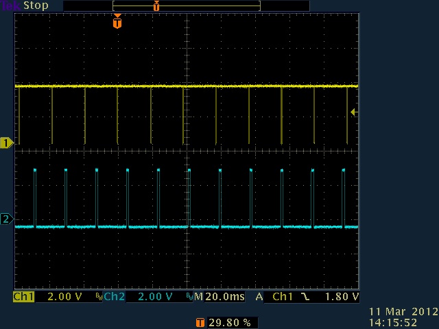
Finally this trace shows the PWM signal going to both motors when a constant speed of 64 is requested. The pwm frequency is about 1200Hz for both. The signal to the motor on port 3 looks noisy due to lack of grounding to the scope.

TEK00013.jpg

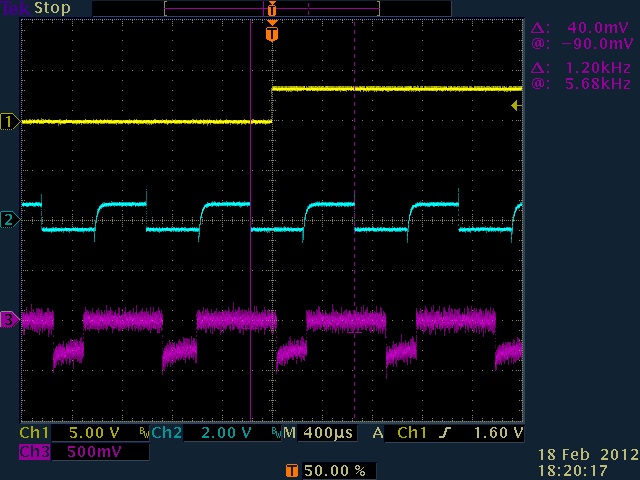
These tests were done using ROBOTC but I would expect the same result using EasyC, this is not dependent on the user code but rather the way user processor and master processor communicate. It’s interesting that the duty cycle for the port 3 motor is not the expected 50%, if I have time I may measure the no load speeds of the two motors to see if they differ, but that will have to wait until tomorrow.

I post this just as information, in practice this has no impact on any competition code that anyone is likely to be running.

2 Likes

For those who would like to know more about the H-Bridge circuit in the cortex and motor controller 29, I found this site that gives a far better tutorial than I ever could.

H-Bridge Secrets

1 Like

Preamble:
Skip over 3wire PWM and go directly to red and black motor wires.
For speed=+127, red motor wire is +, black motor wires is -.
For speed=-127, red motor wire is -, black motor wire is +.
At full +127,-127 speeds, the motor is at 100% duty cycle, so no chopped PWM for variable speed control is seen.

Paraphrase jpearman’s quote above for my own understanding: Scope1
Yellow is digital output: 40ms swaps from 3v to 0v for motor -127, -127.
Blue is port10 red wire: 0v in center line, swaps +,-v closely with Yellow.
Purple is #29MC red wire from port3: swaps from +v,-v with variable lag from Yellow.

  • Lag sequence is 20ms, 19ms, 31.6ms(shown), 10ms.

Scope2: port 10 update delay ~= 1ms

Scope3: try to update motors +127,-127, +127,-127… every 4ms:

  • port10 can follow well.
  • port3 through mc#29: Wow, motor stays in one state for 40-60ms at a time.

** I’ve seen some competition code with “lock motors” routine, that does rapid +127,-127 updates. I’m not sure of the original intent, or its wisdom, but these results might matter there.

Thanks for the great data jpearman!
As you look deeper into the motor PWM duty cycle,
you might also look at port3 to port4 (or any pair of ports 2…9) to see if there PWM are locked.
But probably it doesn’t matter anyway if two motors on the same drive train dont update closer than 40ms…

1 Like

Does the following idea makes sense to update the motor ports once per PWM cycle?
Take a Y cable from Cortex motor port 2,
put the signal pin into a digital input port,
watched by an interrupt watcher, with pseudo code something like this:

while(1){
  Sense_and_Plan();
  Act_yet = GetInterruptWatcher ( 1 )  ; // look for falling PWM edge on motor port
 if (  1 == Act_yet ) {  // or whatever is the correct value to watch for
   Act_yet = 0;  // clear Action trigger, if GetIW doesnt auto-clear
   Act();  // do motor set stuff
 }

I’ll have to experiment with the interrupt watcher stuff, to find out if they auto-clear once they are Got, or what.

1 Like

It may work, however, the problem is that you need to synchronize to two things that are themselves not synchronized. The PWM output from the master processor running every 18mS and the SPI communication from the user processor to the master processor that sends the PWM values for motors 2 through 9.

In my original analysis below I was using ROBOTC, since then I have taken a look at what EasyC is doing whilst debugging dpbailey’s problem with code crashing. I had assumed that EasyC would be communicating with the master processor at the same rate, however, it turns out that EasyC communicates a little less often, every 19mS. They may have chosen this rate as it’s closer to the PWM update rate of the master processor but I have not looked to see if it is synchronized, perhaps I can do that tomorrow if there’s time.

1 Like

I spent an hour looking at a few things today as I was updating to 3.21 now both EasyC and ROBOTC require it for the latest versions, hopefully this version is stable and is not updated for a while (although I have a feeling we have not had the last update yet).

Firstly, all pwm signals are synchronized, I compared motor 2 to all others.

Secondly, here are a couple of scope grabs showing the SPI comms wrt PWM output. The yellow trace is the SPI chip select signal, the blue trace is a PWM signal to a motor. As I had surmised, the SPI runs every 19mS whilst the PWM every 18mS. This is with EasyC, the ROBOTC timing is as I originally posted.

[ATTACH]5464[/ATTACH]
TEK01000.jpg

This is the same thing but with a different timebase.

[ATTACH]5467[/ATTACH]
TEK01001.jpg

1 Like

Terrific. Would you agree with these conclusions of your EasyC data ports 2-9?

  • 90+% of the time, there is a 1:1 matching of SPI update to PWM update.
  • For a randomly timed SetMotor, mean time to SPI update is ~10ms, 19ms max.
  • For a randomly chosen SPI update, mean time to PWM update is ~10ms, 18ms max.
  • Therefore, for a randomly timed SetMotor, mean time to DCchange is ~20ms, ~40ms max.

I mentioned Y-cable in the PWM port to trigger an interrupt for synchronizing,
but that is not the next domain in the chain, SPI is.

Is there any HighSchool competition legal way for the user code to monitor the SPI?
Any constantly changing values in RX buffer to compare maybe?

This is my bad habit, endless refining of one tiny thing already completed, rather than go on to start the other parts of the project…

1 Like

Seems about right.

Yes, for ROBOTC you can use the variable nIfiSPIMsgCounts.

For EasyC you can monitor the last byte of the SPI TX message (or RX message) which increments for each message sent, see this post. Best to do this in a repeating timer that runs every 1mS, should be close enough.

Here are a few SPI messages that were captured about every 140mS, take a look at the last byte of each.

[FONT=“Verdana”]*TX - 17 C9 08 00 00 00 7F 7F 7F 7F 7F 7F 7F 7F 00 00 00 00 00 00 00 00 00 00 00 00 00 00 00 00 01 8D
RX - 17 C9 08 21 7F 01 77 7F 7F 7F 6B 7F 7F 00 00 7F 7F 00 7F 7F 7F 7F 7F 7F 7F 00 00 7F 7F 15 03 1D

TX - 17 C9 08 00 00 00 7F 7F 7F 7F 7F 7F 7F 7F 00 00 00 00 00 00 00 00 00 00 00 00 00 00 00 00 01 94
RX - 17 C9 08 21 7F 01 77 7F 7F 7F 6B 7F 7F 00 00 7F 7F 00 7F 7F 7F 7F 7F 7F 7F 00 00 7F 7F 15 03 24

TX - 17 C9 08 00 00 00 7F 7F 7F 7F 7F 7F 7F 7F 00 00 00 00 00 00 00 00 00 00 00 00 00 00 00 00 01 9B
RX - 17 C9 08 21 7F 01 77 7F 7F 7F 75 7F 7F 00 00 7F 7F 00 7F 7F 7F 7F 7F 7F 7F 00 00 7F 7F 15 03 2C

TX - 17 C9 08 00 00 00 7F 7F 7F 7F 7F 7F 7F 7F 00 00 00 00 00 00 00 00 00 00 00 00 00 00 00 00 01 A3
RX - 17 C9 08 21 7F 01 77 7F 7F 7F 6B 7F 7F 00 00 7F 7F 00 7F 7F 7F 7F 7F 7F 7F 00 00 7F 7F 15 03 33

TX - 17 C9 08 00 00 00 7F 7F 7F 7F 7F 7F 7F 7F 00 00 00 00 00 00 00 00 00 00 00 00 00 00 00 00 01 AA
RX - 17 C9 08 21 7F 01 77 7F 7F 7F 75 7F 7F 00 00 7F 7F 00 7F 7F 7F 7F 7F 7F 7F 00 00 7F 7F 15 03 3A*[/FONT]

1 Like