Hi my name is Sai from 355T and I have been trying to learn the coding and math around odometery but I just can not understand it. It would be really helpful if someone can help me. Thank You very much.
Hey, Sai!
Please refer to the search bar (the magnifying glass) before starting a new topic! (here’s a topic that is already on odometry coding )
It you need more help after that ask me! 

Here is a resource that breaks the math down step bey step.
If the standard odometry math is still too complex, you can also try a more logic-based version. This would still involve the same setup (tracking wheels and all). For simplicity, my explanation will assume one tracking wheel directly right of the drivetrain’s center, and one the same distance directly left. In this version, you would split up the continuous stream of data from your rotational sensor into short instances that can be adjusted during testing. Let’s call the length of these instances “t.” In each of these instances, you would collect data on how much the tracking wheel’s shaft rotated during that instance by subtracting the position the sensor outputs at the beginning of the instance from what it outputs at the end of the instance. Then, using this data (degrees of rotation - let’s call it “dL” and “dR” for left and right, respectively) and the circumference of the tracking wheel, you can solve for how far the tracking wheel actually moved during that instance:
- d/360 converts the degrees of rotation to # of rotations
- multiply this by the tracking wheel’s circumference to get inches traveled by that tracking wheel
Perform this calculation for both tracking wheels. Going forward, I will call the distance traveled by the right wheel DR and the distance traveled by the left wheel DL (don’t confuse these with dL and dR from earlier). At this point you can find how far the robot moved and what direction. The average of DL and DR is your distance moved (I’ll now call it M). For what direction it moved you first need how much it turned in the instance:
- W = the distance between the left and right tracking wheels (width)
(DL-DR)/W gives the angle turned in radians.
To convert this to degrees use degrees= (180*(radians turned))/pi because there are 2pi radians in a circle and 360 degrees in a circle. Let’s call the degrees the robot turned in the instance DT.
Now, you will need to use 3 variables for the robot’s position and orientation on the field that should be established towards the start of the code. Let’s call the variable of the robot’s x-position x and the one for its y-position y. The variable for the direction the robot is facing can be called F (facing). At the start of the match, your robot’s position can be considered (0,0) and it’s facing can be considered 0 degrees.
After each instance, you will need to use the amount your robot turned (DT) and the distance it moved (M) to update the direction it is facing (F) and its position on the field (x and y). For the direction it is facing (F), add the degrees the robot turned in the instance (DT) to your “F” value and set that as the new “F” value. After that, you can now split the distance the robot moved (M) into its x and y components:
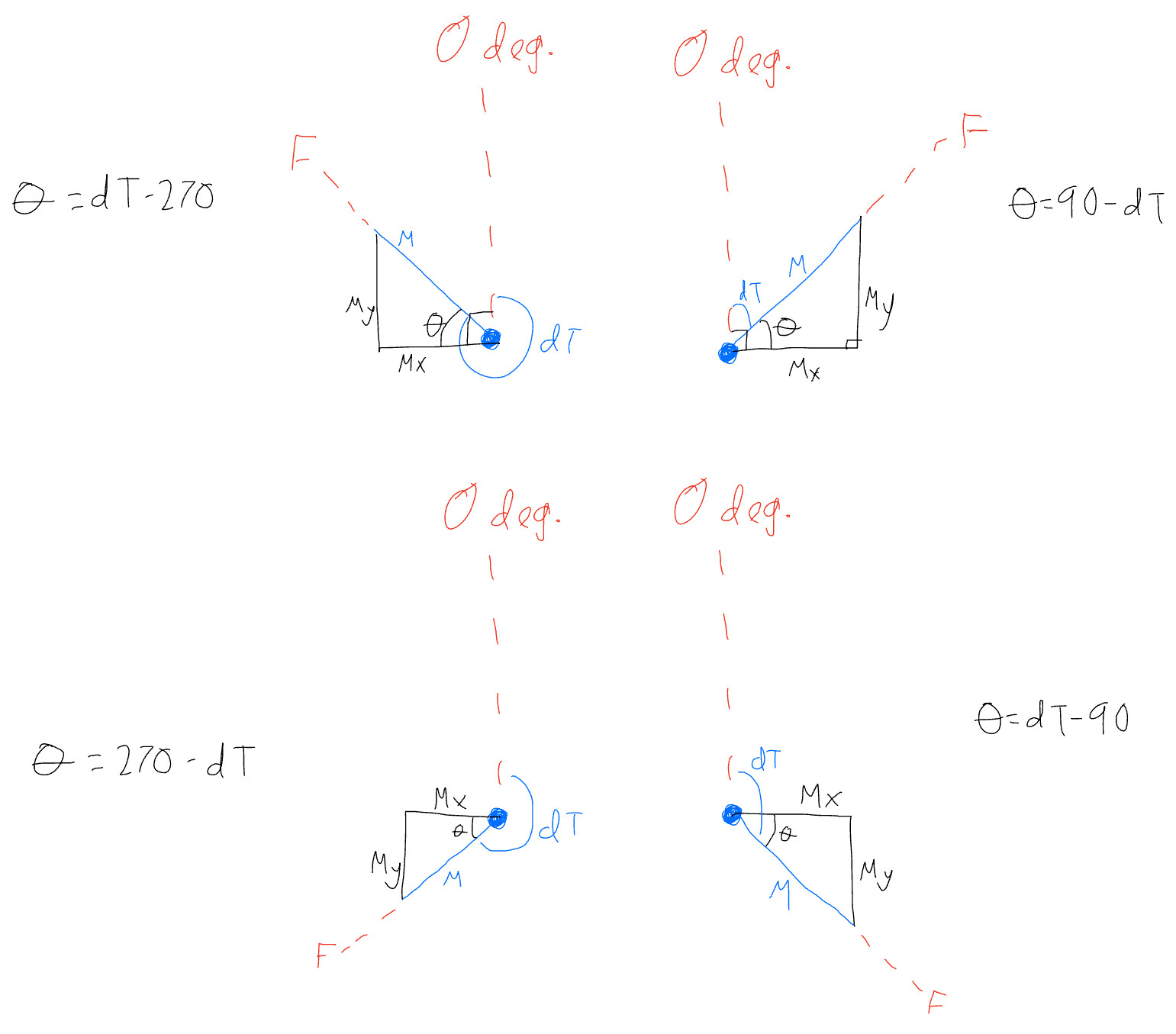
There are some shortcuts but this diagram and explanation won’t use them for simplicity. As you can see on the diagram, depending on which quadrant the robot’s direction faces there is a different formula for finding the angle needed to split M into x and y components (for scenarios where the robot is facing a multiple of 90, there is no splitting needed because the M is already vertical or horizontal). After using the correct formula for the angle (referred to as theta in the diagram), Msin(theta) gives the y-component and Mcos(theta) gives the x-component (for the ones facing quadrant 3 or 4 make your answer negative for the y-component and for the ones facing quadrants 2 and 3 make your x-component negative — the necessity for this comes from the method I used to potentially make understanding easier). Now that you have the x/y component(s), add the y-component to your y-position (y) and add your x-component to your x-position (x).
Repeating this loop of instances should get you a constantly updating approximation of your robot’s position (unless I made an oversight or error somewhere - feel free to correct it).
Side note: If you use someone else’s work for your robot, make sure to give them credit in your notebook AND prove you actually understand it instead of just copying it. (Remember the VEX competition’s ultimate goal is learning, so copying without understanding would not only go against the game but also against you.)