I want to help with anyone trying to build their own odometry. First of all, my example code simulation below is based upon the odometry unit center:

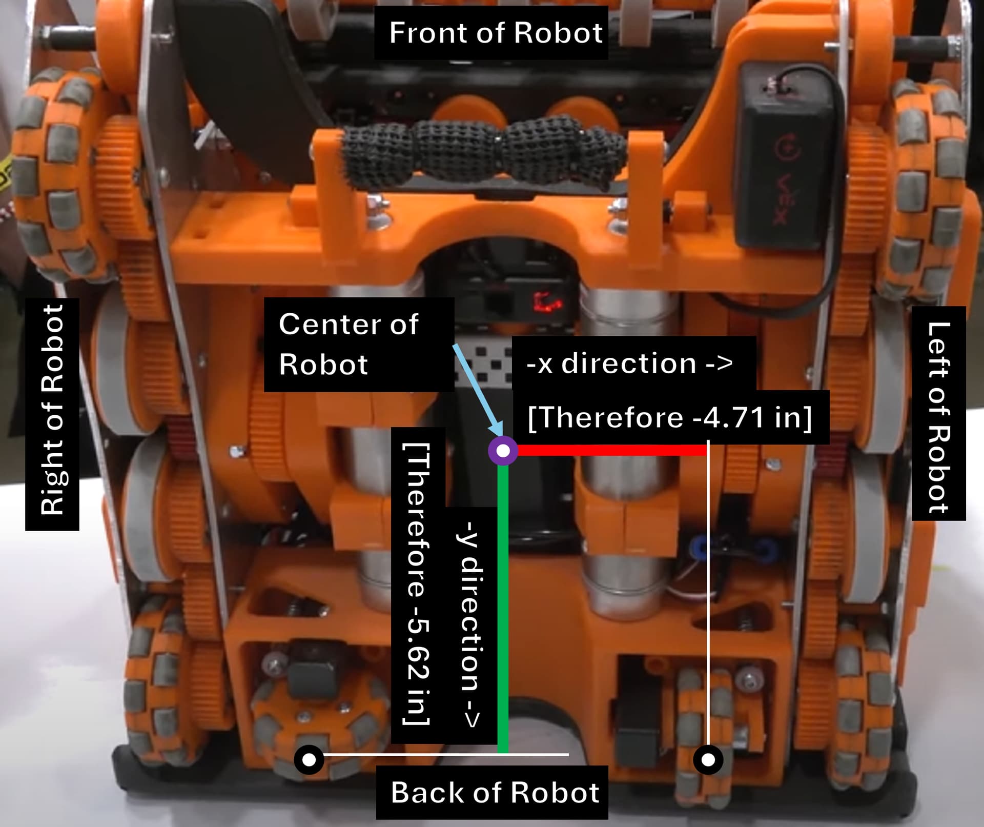
The following illustration shows the center of the odometry unit. The odom unit center is the virtual intercept of the perpendicular faces of the odometry trackers. The measurements is from the center of the odom unit to the designated tracker distances.
The forward tracker is always offset right/left from the center of the odometry unit center, while the sideways tracker is always forward/backwards from the center of the odometry unit.
Based upon the following illustration above, with 2.5189 inch wheels, the forward tracker being offset to the right, and sideways tracker being offset back of the odometry unit:
python
# Configuration

encoder_ticks_per_revolution = 360

wheel_radius = inches_to_meters(2.5189) # meters (can be wrapped from inches via inches_to_meters)

odom = WheelOdom()

odom.set_physical_distances(inches_to_meters(1.5),inches_to_meters(-4.468)) # (forward tracker position [+right, meters], sideways tracker position [+forward, meters])
It’s important to note that this example does not include a transformation to the center of the robot. Either you must program a transformation from this point to the center of the robot, or you should just place the odometry wheels such that the odom unit center is center of the robot. Note that traction wheels will shift the center of the robot towards its position
From this we will set the starting position of the odometry unit center to 0, 0 meters with a radius of 0 radians:
odom.set_position(0, 0, 0) # Reset to 0,0 meters and a yaw of 0 radians
Then, I will run a simulation where I simulate encoder ticks of the odometry wheels, alongside the yaw of the robot, and translate it to meters:
# List of updates: (forward_tracker_pos, sideways_tracker_pos, new_orientation_rad)
updates = [
    (encoder_ticks_to_meters(750, encoder_ticks_per_revolution, wheel_radius), encoder_ticks_to_meters(0, encoder_ticks_per_revolution, wheel_radius), np.pi/4), # forward tracker sensor reading of 1, yaw to pi/4
    (encoder_ticks_to_meters(1500, encoder_ticks_per_revolution, wheel_radius), encoder_ticks_to_meters(0, encoder_ticks_per_revolution, wheel_radius), 0), # forward sensor reading of 2, yaw of 0
    (encoder_ticks_to_meters(750, encoder_ticks_per_revolution, wheel_radius), encoder_ticks_to_meters(0, encoder_ticks_per_revolution, wheel_radius), 0) # forward sensor reading of 1, yaw of pi/4 <- notice the robot goes in reverse
]
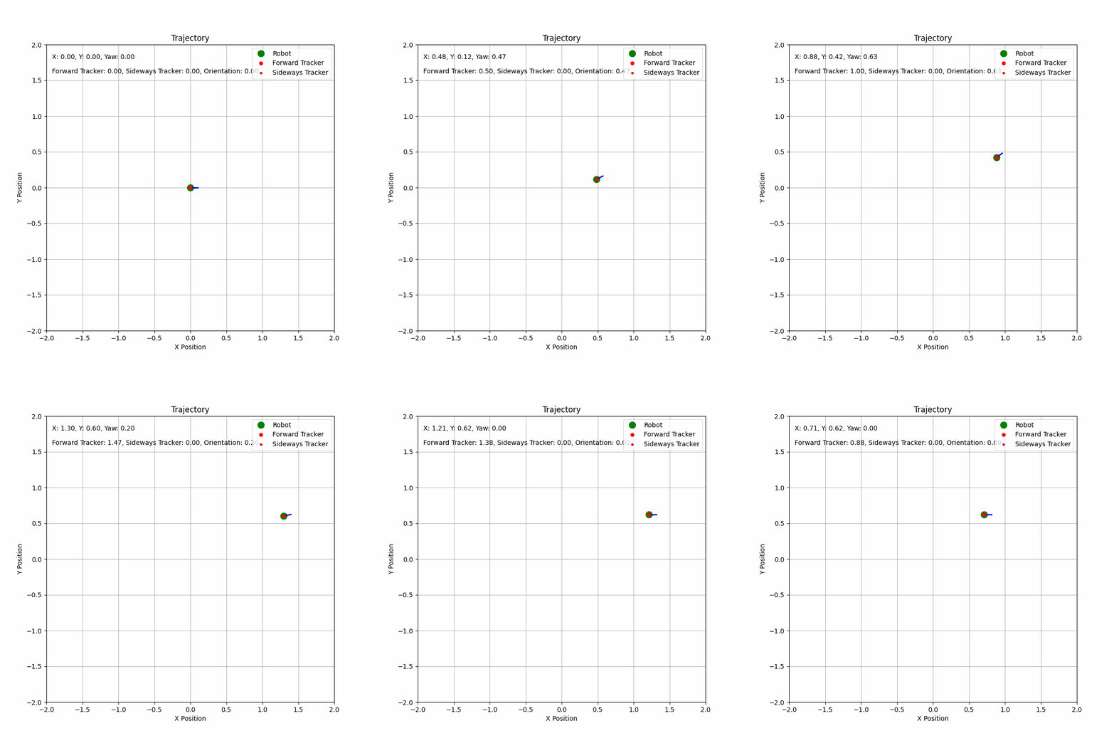
This is the following result:
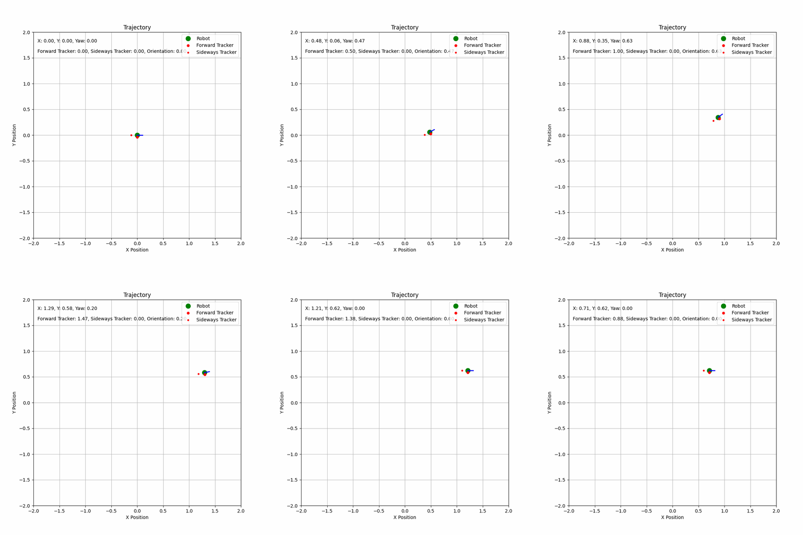
As you see, this is arc-based odometry. Its tracking is a lot more accurate than linear-based odometry because it respects the motion of the robot.
You can mess around with the odometry class and you can translate it to C++ if you’d like via the link below. Note that a yaw of 0 radians is facing the +X axis: