Periodic V5 Motor Encoder Anomaly

Setup:
Spin a V5 motor at 6 volts in a 50ms loop. Print out the raw encoder values along with the system high resolution timer (for a time reference). Do the math to find out how many raw ticks you get per 50ms loop.

Observations:
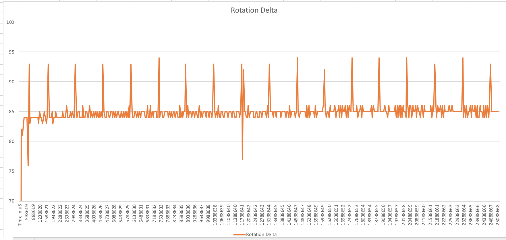
I’m seeing 83-86 raw counts per 50ms loop, mostly 84 and 85 once we’re up to speed. I see a tick up to 93 or 94 raw counts, sometimes at 145003us intervals, and sometimes at 140003us intervals. It’s very consistent.

I’ve tried this with VCS and RMS, both C++ and Python. Same results. I’ve also left the counter running versus resetting it every loop and using a different motor. I’ve set the motor speed with voltage and percent power, read the encoder in degrees, raw, and rotations. No change. I also thought that maybe the debugger or console might cause a periodic delay, but disconnecting and pushing the output to the V5 Brain LCD didn’t change anything either.

Any ideas on what I’m seeing, and if it’s expected or not?

int main(void) {
    // Start here
    motor1.resetRotation();
    motor1.spin(vex::directionType::fwd,6,vex::voltageUnits::volt);
    
    int loop = 1;
    timer t = timer();
    
    while(loop < 500) {
        std::cout << (t.systemHighResolution());
        std::cout << ("  ");
        std::cout << (motor1.rotation(vex::rotationUnits::raw));
        std::cout << ("\n");
        
        loop = loop + 1;
        
        sleepMs(50);
        
    }
     
}

Sample output (the first and last rows are the odd counts, the last two columns are calculated in Excel):

Time in us Raw Encoder Count Time Delta Rotation Delta
3138624 4831 50000 93
3188624 4916 50000 85
3238624 5000 50000 84
3288624 5085 50000 85
3338624 5170 50000 85
3388624 5254 50000 84
3438625 5338 50001 84
3488625 5422 50000 84
3538625 5508 50000 86
3588625 5592 50000 84
3638625 5676 50000 84
3688625 5761 50000 85
3738625 5846 50000 85
3788625 5930 50000 84
3838625 6014 50000 84
3888625 6100 50000 86
3938625 6184 50000 84
3988626 6269 50001 85
4038626 6353 50000 84
4088626 6438 50000 85
4138626 6522 50000 84
4188626 6607 50000 85
4238626 6691 50000 84
4288626 6776 50000 85
4338626 6860 50000 84
4388626 6945 50000 85
4438627 7029 50001 84
4488627 7114 50000 85
4538627 7198 50000 84
4588627 7291 50000 93
1 Like

I’m not sure exactly what the question is, however, there are 1800 counts/rev inside the motor so you would expect an average change of 90 counts every 50mS. The motor communicates with the brain approximately every 5mS and then there are other background processing loops that mean the values you will see will have a certain amount of jitter. The speed of the motor running with 6V will depend on the load, so if the motor has no load it may well operate near to full speed. So yes, I think what you are observing is probably expected.

I supposed what I’m curious about is that jump to 93 counts in the 50 ms period every 1.4 to 1.45 seconds. I’m seeing pretty consistent raw counts of 84 to 85 every 50ms, but then it jumps up by 10% or more in that same period.

I could run that loop for 5 minutes and you’d see that 10% spike in encoder counts hitting consistently, and the motor is running with no load.

I expect to see a little variation in the counts, but not that big of a jump, and not at such a regular cadence.

If I graph the encoder counts, measured every 50ms, it looks like this:

29%20PM

That periodic jump is unexpected.

So the issue is that the motor is determining the 5mS communication rate where the brain has its own background processing timers. If for some reason the brain processing missed the data from one message you would see a jump, the following sample would probably be less. That’s what I assume you are seeing.

Thanks @jpearman. I appreciate your insight + experience.

One last little experiment. I connected a Quad Encoder to the shaft and measured the output of both the V5 and Quad encoders at the same time.

After 21 full rotations of the shaft, both encoder counts (converted) were exactly the same. The Quad encoder didn’t have that periodic “catchup” seen on the V5 encoders.

(V5 on top, Quad on bottom)

09%20PM

I’m wondering if there’s a loop frequency that will minimize what I see on the V5? If I were trying to determine rotational velocity with the raw encoder counts, that jump would fool the algorithm (PID, or whatever) into thinking that it had sped up.

I think, anyway…

First, I’d try to sample both values first, then to print them to rule out (or limit) the case where one more update comes between the time capture and the rotation capture. But if that was the case (or a general jitter that would cause your sample point to fall just before vs. just after another update), you’d see an about-equal-sized drop on the next sample and I don’t see that in your charts.

So my best guess is that the motor clock is running a little faster. AFAIK the motor MCU has no precise time reference (crystal oscillator) and runs on (at best well calibrated) RC oscillator, with the frequency easily off by 1% or more. As the motor samples its internal count every 5ms (of it’s internal time) and send it to the brain, each such sample is about 8 ticks bigger than the previous. The brain ditifully receives all the updates and keeps the last known value (with a granularity of 5ms worth of rotation, or about 8 ticks). Your program queries this value every 50ms, that is, roughly every 10 updates from the motor, but if the motor clock is 1% faster, it would sneak in 11 updates into about every 100th iteration of your program (5s).
What you see in those 5 seconds (or 1.4s in your case for about 3% motor clock drift) is that your sample point gradually drifts across the 5ms window of the motor’s sample point, then you cross the boundary (see one more sample) and your 5ms drift window resets.
If you were sampling every 5ms, you’d see delta values like 8,8,9,8,8,8,9,8,8,16,8,8,9,8,…
If you were sampling at 1ms (assuming the brain would let you), your deltas would be like:
0,0,0,8,0,0,0,0,8,0,0,0,0,8,0,0,0,8,0,0,0,0,8,0,0,0,0,8
(i.e. 4 zeros most of the time, but only 3 zeros when your clock base windows cross)

That fits what I’m seeing, thanks for the great insight.

Further, if I capture the same numbers with two motors attached, I still see the same periodic jump in encoder measurements, but each motor has a different frequency of that periodic jump. Assuming the Brain is servicing the ports at the same rate, but offset by some constant process time (per port), I think the clock-drift hypothesis still fits well.

Just to clarify, your program is likely sampling the motors at the same rate, but the brain isn’t. In fact, the brain is very passive when it comes to receiving data from the motors. The motors initiate the communication on their own and they can even happen to all send the data at the same time (in the unlikely case their clock align).
The brain receives the data from the motors (or V5 devices in general) mostly in hardware. There are >20 hardware UARTs, each having direct DMA capability into dedicated buffers (allocated from a special On-Chip-Memory area of the Zynq FPGA), so even if there are bytes coming at the very same moment on each of those many ports, all of them will make it to their respective buffers.
This aspect of the V5 architecture is really genius.

Thank you, that’s an important point and clears a few things up for for me.

So with that architecture the compiled code isn’t sampling or interfacing directly with the motors at all via UART, it’s looking at the memory locations that the encoder values are ending up in, pushed by the V5 motors themselves on their own clock.

It’s a really powerful platform - I don’t think it gets the credit it deserves in that respect.