Up to now this thread was focusing on theory and some speculations, but now many teams already went through the multiple designs and have solid launchers on the working robots. So what are the practical lessons we have learned?
There is a number of recent threads where people share their successes with two-motor non-flywheel launchers. There is also a number of threads, where (mostly younger) teams share their painful experiences with the flywheels. It doesn’t have to be that way.
I think continuous flow flywheel is a superior type of launcher. Experienced teams could build award-winning non-flywheel launchers that will easily beat an average flywheel, but if they put their skills into perfecting the flywheel design, I think, they could do even better.
Most of the problems that people are experiencing with the flywheels are due to the excessive friction, too much of the ball compression, and even more friction as a result of that.
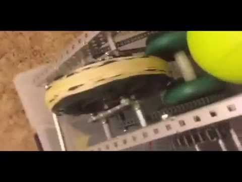
Here is our attempt of addressing these problems by building an extremely low-friction flywheel prototype:
Earlier vamfun presented a convincing argument that a single flywheel with large moment of inertia, running at twice the speed of the dual flywheels, is an optimal solution. That is, if you can successfully manage the friction.
The purpose of this video is to show that two 393 motors provide enough power for a single flywheel launcher. There are two turbo motors driving flywheel with 19.2:1 external (46:1 total) gear ratio. Not only there is enough power to reach the high goal, but flywheel rotates way too fast and keeps overshooting. We will fix that later.
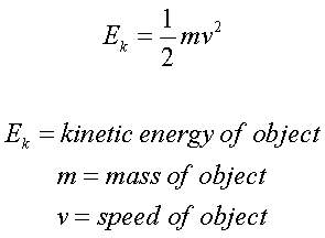
I haven’t done precise measurements, but from the crude video analysis it looks like if you feed the balls at the right speed you could consistently hit target while shooting 4 balls in about 2 seconds. If you feed balls as fast as you can - it will launch four balls in just over a second with the first three overshooting, and the last one falling slightly below the target. Clearly at that speed flywheel has enough kinetic energy stored to give the first three balls more than enough speed. Obviously, for this design to be practical the feed rate needs to be program-controlled like 323Z does.
Single flywheel concept also fits nicely with reducing robot’s weight, size, and the number of the moving parts. The last is especially important, because it will let you reduce the number of axles.
Technik jr started building our first prototype with 21:1 total ratio driven by two force motors. It could launch balls only a few feet away. It would not even spin up with one force motor. Getting down to one force motor was relatively easy with just better build procedures, but moving further was much harder.
Power loss at each axle is proportional to (torque due to friction) * (angular velocity). Therefore even 0.5 in-lbs in resistance at the flywheel bearings would amplify 21 times to 10.5 in-lbs around the motor axle ( out of maximum available ~15 in-lbs stall torque). However, you want to run motors at only ~10% of the max load for the best efficiency, spinning at about ~85% of their idle speed (see the graph in the post below).
According to our estimates for a single 5" flywheel that would require ~ 30:1 total gearing. Since each axle introduces friction, you want to reduce total number of axles. Both speed and turbo motors could be used with just three axles and require ~19:1 (speed) and 12.5:1 (turbo) external gear ratio. I think turbo is a better choice because smaller torques will flow through the system.
So the next task was to actually reduce the friction so much that the launcher could be spun up with a single speed and, eventually, turbo motor. Technik jr and teammates have developed better alignment procedures and it let us, at least, start with a single speed motor, but launching balls or starting up with a single turbo motor was still unreachable. There was just too much friction between square axle and the bearings, which would only increase when flywheel would try to compress the ball.
So we did two things: first we introduced a pre-boost stage to pre-compress the balls at the slower speed, when more torque is available, and second, and more important, we figured out how to build a better bearing. I still cannot reveal the secret of how team did it, but I could give you a hint that they found an almost a perfect VRC-legal part for this mission, broke 1/8, and stripped 13/64 drill bit while perfecting the implementation