I’m one of the programmers for our team, and I was wondering how we would use the AI vision sensors to help position our robot. Our team wants to, but I have no clue how to code for that, or any type of positioning at all. My partner is doing odom, but I don’t really get how he does it either. I know the basics of C ++ (what we code our robot in) but don’t know how to code it. Any help with programming, or more specifically, using AI sensors for programming positioning somehow simultaneously with odom, would really help!
See the VEX reference library section if you haven’t looked at this already:
First thing to try out is the AI Vision Sensor Configuration Tool within VEXCode. This is particularly useful for seeing how well the sensor works with distance and lighting. I would do this first before trying to write any code as the AprilTags are on the smaller side.
There’s a sample program in VEXCode using AprilTags: “Detecting AprilTags (AI Vision)”. They have this in Python and C++.
If you have reasonable existing odom code then you already know where you are on the field. Question then is what additional info the vision sensor gives you …
In theory you know where the goals are and the size of the AprilTags so with some trig you can turn the sensor’s X/Y/W/H readings into a very rough calculated position of the robot on the field (at least assuming you know what face of the goal robot is facing). However:
- You will also need to take mounting height, angle etc. into consideration as these become more important the closer you get. This gets complicated very quickly
- You are susceptible to standard camera-based sensor challenges like dropouts, false positives, motion artifacts, limited refresh (update) rates. etc. so will need code to intelligently filter / reject readings and slow the robot down while taking sensor readings
Most likely you’d need a distance sensor for the distance to the goal and the AI vision sensor would give you a relative heading for centering the robot. You could then use some kind of heuristic (logic) to decide if your odom code has drifted enough that it requires the equivalent of a wall/goal bump. I wouldn’t throw any of these other techniques away though.
Final note: AprilTags are so close to the ground that any strategically placed pins/cups block them. Probably not an issue for auton period, but driver assist would be not guaranteed.
Anyway, hope this helps on the sensor part of it at least.
I would recommend focusing on odom first as it is a really useful to know for all compititions. I think I broke Odom down into polar coordinates which is really useful and simple. Check out the Wikipedia page on them and learn how to convert from cartesian(normal) and polar coordinates.
Here’s an initial attempt at doing the “forward” detection, meaning learning where the goals are using existing odom. In reality of course you want the opposite - knowing how to correct your odom based on fixed (or somewhat fixed) markers.
For this demo I’m using 1d Kalmans (Kalman Filter | Purdue SIGBots Wiki) in X and Y. Process noise is based on approximation of odom drift (~0.05mm / 10ms update) and measurement noise variance was set fairly high at 1m per 10Hz camera update.
The triangulation logic is fairly basic. For distance I use a mix of tag height (in pixels) and offset from bottom of image depending on low, middle or high goals. Relative heading is based on offset from center of image in X although this should really take camera mounting pitch into account. So improvements possible here.
Some challenges:
- AI snapshot update rate: I haven’t been able to find a way to know when exactly a snapshot gets updated. Based on looking for changes in detected objects it seems to average at around 10Hz. Based on this I take snapshots at a higher rate looking for any detectable updates or timeout at 100ms and pass this on as a fresh detection. For filtering this is important or you’ll feed it with spurious accuracy
- Spurious detection: You want a robust way of rejecting false positives
- Re-used tags: All the faces on a goal use the same tag, so knowing which face you’re working with requires use of the inertial sensor and some math. However, I think limiting the number of tags used was necessary because of the previous point
I wanted to see how well this worked without specifically visiting each goal (ie getting a mix of glancing views and actual visits).
For coordinates I use North-East convention (X is North, Y is East, 0deg is North increasing clockwise). For the results 0,0 is far left of blue alliance wall (actually under perimeter).
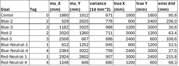
The ones with the high (>100mm) error distances are where there was only a brief fly-by.
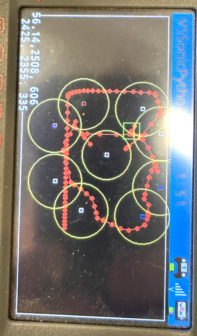
Color code:
- Green Square: Current robot location
- Red line and dots: robot trail
- Blue Squares: Blue alliance goals
- Red Squares: Red alliance goals (note one has a blue trail inside of it showing how the approximated center moved)
- Yellow circles: Confidence (robot has been stationary for about a minute so these have all grown to maximum allowable for rendering anyway)
Results somewhat encouraging anyway for looking at the reverse process (odom drift correction).