Every popular robotics or micro-controller forum has a thread where people argue if commanded motor power level linearly translates to motor speed, force, or something else.
The correct answer to this question is: it depends. It depends on many things.
https://vexforum.com/attachment.php?attachmentid=9621&stc=1&d=1444196372
Each motor has a nominal (or idle/no load) speed. Even without load it still draws some current (consumes some power). It spends it to counteract whatever little friction its gears have and heats up its electromagnet coil a bit because the wire has non-zero electric resistance.
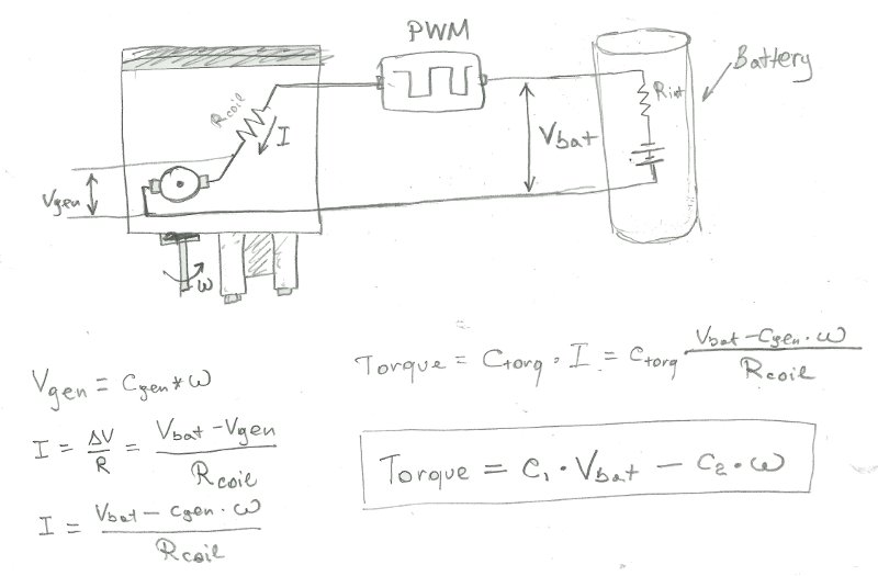
When motor’s rotor spins at a speed (w) it acts as a little electrical generator that would produce Vemf = Vgen, which is just slightly less than battery voltage Vbat, and we would get some small current going through its Rcoil from higher to lower potential. The power converted to mechanical energy is Vgen*I and the power to heat coil is (Vbat-Vgen)*I. Eventually all that energy will convert to heat.
Alternative way of thinking may be that to counteract friction in the motor you need specific Torque, which has linear relationship with the electric current (via some Ctorq coefficient for this particular motor). Once you know the current you will know voltage drop over the motor’s internal resistance Rcoil and then the motor could speed up up to speed (w) that corresponds to Vemf=Vgen via some constant Cgen, until Vemf matches remaining voltage differential (Vbat-Rcoil*I).
One way or another, for each load (torque) and supply voltage (Vbat) motor settles on a speed (w), see 393 motor curves. The important result is that without PTC kicking in we expect linear relationship between torque, Vbat, and w (Torque = C1 * Vbat - C2 * w) where C1 and C2 some coefficients for our specific motor. To keep our formulas simple and motors running all the time it is a good idea to manage motor load to prevent PTCs from tripping anyways.
Now we have to consider effects of PWM. Essentially, motor controller connects motor to the power supply Vbat for only a fraction of the time. One way of thinking about it that you still could have full force (Vbat) but have current flowing only part of the time, thus getting access to a fraction of the max power. However, since motor rotor’s moment of inertia acts as a mechanical capacitor that smoothes voltage=0 and voltage=Vbat periods into an average effective voltage we could say that we have access to the fraction of the supply voltage Vbat corresponding to the duty cycle.
According to this thread MC29 has non-linear relationship between commanded power level and actual output power level. Here is an example from VEXPro thread. Turned out that VEXPro was actively monitoring motor speed and throttling motor power to achieve linear relationship, while MC29 was letting laws of physics inside its less than perfect circuit with simple firmware define the shape of the curve:
https://vexforum.com/attachment.php?attachmentid=6136&d=1337552779
To make things more interesting for us here is a quote from Paul:
So, you may in fact find that your old MC29 will behave differently from the version with the newer firmware.
However, if you know exact parameters of the specific hardware pieces you have, it shouldn’t matter. The curve shape is predictable and known. If we create a lookup table (or try to fit a polynomial) between commanded and actual values we will know the effective voltage supplied to the motor at all the times.
Since we can estimate the speed of each motor, and we know commanded motor voltage - we can calculate output torque and, therefore, predict acceleration and the future path of the robot. The takeaway is that MC29 non-linear curve requires some additional coding and testing from us, but is not a showstopper at all.