My knowledge of the rolling resistance is limited to the wikipedia article and a few other sources I could find on the internet. Most research is done about soft inflated tires running on the hard surface. The dominant factors determining Crr in that case are tire temperature and pressure with vehicle velocity taking the third place and can actually slightly decrease with higher velocities before going up again in some scenarios (see fig 2.23 on pg16).
In cases where tires are firm, the dominant opinion is to use constant Crr and that velocity doesn’t need to be considered at all.
We have slightly different situation with firm tires running on somewhat soft surface. Few sources that consider rolling resistance on the soft surfaces don’t even talk about velocity in that context. The best source on this subject analyzes aircrafts running on the grass and soil surfaces and is hardly applicable to our scenario.
So, here is how I understand it after looking through the above links:
https://vexforum.com/attachment.php?attachmentid=9679
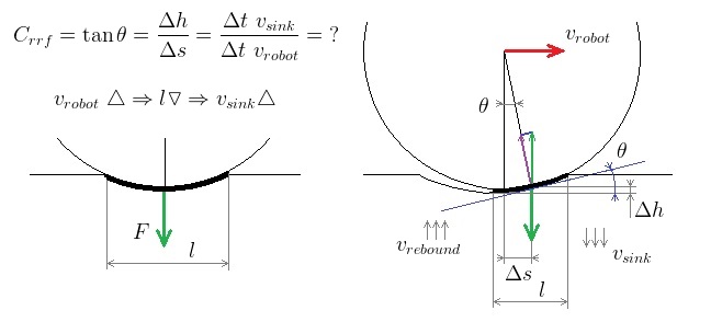
When robot is at rest it makes an indentation in the foam surface with the depth somehow proportional to its weight. The section of the foam-to-wheel contact is depicted by (ℓ).
When robot goes forward with speed (Vrobot) it starts climbing out of the hole. As it moves toward the edge the new section of the foam will starts compressing and will go down with some speed (Vsink). The faster the robot moves - the closer it gets to the edge, and the smaller is the new section of the floor (ℓ) that now supports robot’s weight. The smaller that section is the larger will be the pressure and the faster the foam will sink.
For each value of velocity (Vrobot) there will be a point of equilibrium when foam sinks down just as fast as the robot advances. If we measure value of Crr it will correspond to a slope at an angle (theta) such that it takes the robot to advance distance (delta s) just as fast as the foam sinks to the depth (delta h). Without having analytical models, the simplest way to determine relation between Vrobot and Vsink increases is, essentially, by running an experiment to determine the value of Crr at various robot velocities.
If I could persuade technik jr that I really need chassis finished to run this experiment, and we have chassis done … then I’ll try it. But it will, probably, be much longer before chassis are properly aligned and my measurement task is fully debugged to get enough sensitivity for a conclusive Crr vs velocity plot.
Edit: almost forgot to mention the most important part: (Cf) coefficient that includes (Crr) is the only coefficient that does not fully depend on the robot as it might change from field to field. So the smart thing to do is to let filter estimate this coefficient as part of its state. The robot will start with hardcoded average value for (Cf) then drive a couple of feet straight forward and estimate correction for (Cf) on this specific field. By the time robot starts making turns and needs more precision it will already have refined value of (Cf). If it is, indeed, a case that (Crr) considerably depends on the speed, then we will see the pattern in the drifting filter estimates of (Cf) at various speeds and will be able to easily fix equations.