Simple Programming Questions

Start by having your Programmer sign up with the Vex Forum, and start looking through the recent posts on Programming.

Have the programmer look at the Goals your Bot is to achieve, and ask questions of the other programmers on how to solve the programming to accomplish those goals.

We’re really a friendly group… Really…

I looked at all of the Carnagie Mellon videos for RobotC and have looked at the sample programs trying to learn how to program our quadrature shaft encoders. Moving forward and right turns are no problem, but we cannot initiate a left turn. The way our encoders are mounted the left counts up and the right counts down with forward motion. Everything works fine when we are initiating movement with positive values on the left encoder, but we cannot seem to figure out how to get RobotC to work with negative values.

Is there something I need to do different from the other code I have used with positive values besides tossing a negative sign in front of the value?

If all else fails I plan on flipping the right encoder over 180 defrees with the shaft going in the other side to get it to count up with forward movement, but I would rather leave it mounted as is and figure out what we are doing wrong.

Below is our test code, it does not execute the last command.

Thanks in advance!

#pragma config(Sensor, dgtl1,  rightEncoder,   sensorQuadEncoder)
#pragma config(Sensor, dgtl7,  leftEncoder,    sensorQuadEncoder)
#pragma config(Motor,  port2,           rightMotor,    tmotorServoContinuousRotation, openLoop, reversed)
#pragma config(Motor,  port4,           armMotorleft,  tmotorServoContinuousRotation, openLoop, reversed)
#pragma config(Motor,  port5,           armMotorright, tmotorServoContinuousRotation, openLoop, reversed)
#pragma config(Motor,  port6,           intakeMotor,   tmotorServoContinuousRotation, openLoop)
#pragma config(Motor,  port7,           leftMotor,     tmotorServoContinuousRotation, openLoop)
//*!!Code automatically generated by 'ROBOTC' configuration wizard               !!*//

//+++++++++++++++++++++++++++++++++++++++++++++| MAIN |+++++++++++++++++++++++++++++++++++++++++++++++
{

  //Clear Encoders
  SensorValue[rightEncoder] = 0;
  SensorValue[leftEncoder] = 0;

  while(SensorValue[leftEncoder] < 360)  
  {
    motor[rightMotor] = 100;
    motor[leftMotor] = 100;
  }
  wait1Msec(250);

    //Clear Encoders
  SensorValue[rightEncoder] = 0;
  SensorValue[leftEncoder] = 0;

  while(SensorValue[leftEncoder] < 275) 
  {
    
    motor[rightMotor] = -63;
    motor[leftMotor] = 63;
  }
   wait1Msec(250);

   //Clear Encoders
  SensorValue[rightEncoder] = 0;
  SensorValue[leftEncoder] = 0;

  while(SensorValue[leftEncoder] < 330)  
  {
    //...Move Forward
    motor[rightMotor] = 100;
    motor[leftMotor] = 100;
  }

  wait1Msec(250);

   //Clear Encoders
  SensorValue[rightEncoder] = 0;
  SensorValue[leftEncoder] = 0;

  while(SensorValue[leftEncoder] < -120)  
  {
    
    motor[rightMotor] = 63;
    motor[leftMotor] = -63;
  }
   wait1Msec(250);
}

This code

   //Clear Encoders
  SensorValue[rightEncoder] = 0;
  SensorValue[leftEncoder] = 0;

  while(SensorValue[leftEncoder] < -120)  
  {
    
    motor[rightMotor] = 63;
    motor[leftMotor] = -63;
  }

Should be

   //Clear Encoders
  SensorValue[rightEncoder] = 0;
  SensorValue[leftEncoder] = 0;

  while(SensorValue[leftEncoder] **>=** -120)  
  {
    
    motor[rightMotor] = 63;
    motor[leftMotor] = -63;
  }

Assuming the left encoder counts down. It starts at zero so you need to run the motors when it is the range 0 to -120, ie. > -120

I have been working with the Template Program I put together for owenhunt11 and the COMPETITION SWITCH SIMULATOR. The order and method of the Cortex’s program is different than what jpearman has listed in Post #1 of thread, Tournament Order of Progression - unofficial answer.

What I have found is the COMPETITION SWITCH SIMULATOR, defaults to ENABLE and DRIVER, immediately after the Program Download is performed and my attached program indicates that the Initialization function is never called.

When the COMPETITION SWITCH SIMULATOR is set to DISABLE, the Cortex is Reset, giving the prompt, “Field Control Competition Project.”, ( which also clears all the global variables ), and then Calls the function, Initialize.
My Bumper Switch code is running at this point and One switch or the Other ( or neither ) can be pressed… When the AUTONOMOUS Mode is selected and the Robot is set to ENABLE, the Autonomous function can use the chosen Bumper Switch to determine which set of Autonomous Code to Execute…

Bottom line is that when the COMPETITION SWITCH SIMULATOR is set to DISABLE, the Cortex resets all Global Variables, and calls the function, Initialize. When the COMPETITION SWITCH SIMULATOR is set to ENABLE, the DRIVER or AUTONOMOUS function is then called, depending on which Button is selected in the COMPETITION SWITCH SIMULATOR.

Global Variable set in the function, Initialize, will still be set in the DRIVER or AUTONOMOUS function, but if the AUTONOMOUS function modifies any Global Variables, they will be Re-Initialized by the function, Initialize, before the function OperatorContol is called. Using the Undocumented Function [FONT="Courier New]IsAutonomous()[/FONT], custom Initalization code could be made that would differ for Autonomous Mode and OpperatorControl Mode, but only if the Mode is set before, or very shortly after the DISABLE Mode is set.

As long as the Robot is Powered Up, and Field is set to DISABLE, this Code should work for Autonomous Selection. It would fail if the field was set to ENABLE, then reset to DISABLE, because a second call of the function, Initialize, and no one there to press a Button.

Also, you can not pass Global Data from the Autonomous function to the OperatorControl function, except maybe through the “GlobalData” array.

The real COMPETITION SWITCH may perform differently, and the Order of these step might vary at some point, thus making this selection method unreliable.

If All Else Fails, you can use the Vex Jumpers in place of the Bumper Switches, because they could be re-read at any time during the Match…
owenhunt11_001a.zip (4.49 KB)

No, I think it’s pretty much as you describe, we had discussed once before.

Things can get even more messed up if the robot is powered before being connected to field control, that’s why the best situation is to connect first, power up second.

I’m afraid IMHO that EasyC is pretty messed up, it would be nice to know the backstory of why what appears to be a full processor reset was needed each time the robot is disabled.

WOW!! I don’t remember this thread, I think they’re all running together now…

At Least the Start-Up seems consistent when you connect, then Power-Up…

It has been my experience with Embedded Systems, that a Full Reset is performed, when the Controller is in an Unknown, Potentially Corrupted or Corrupted ( Watchdog Reset ) State. Thus returning the Controller to a ( mostly ) Known State. I would love to know the Back Story too…

After more experimentation, it appears that the Reset is CORRECTION: A Total Reset… See Post #15.

Back with another question.
So in EasyC V4, can you call the OperatorControl function just like any other? (assuming you are using the competition template)
If so, how does it work?

Yes, EasyC unregisters the interrupt handlers and then does a core reset (which is distinct from a full system reset).

There is a way of retaining data but is not something that EasyC (or ROBOTC) provides as standard. The STM32 provides 84 bytes of storage known as the backup registers, I was playing with them a few months ago, they are arranged as 42 16 bit registers that can be theoretically powered from a coin type battery (VEX did not implement this) and retain data after reset. I will post some code showing how to enable and use them sometime. In VEX’s implementation data is not retained after a power cycle, flash needs to be used for that.

I have another programming question, I want to be able to press one button on my controllelr and my lift will automatically go up to say 18 inches and then i press another button and it goes up to 30 inches. I have almost all the vex sensors I just do not know how to write the code

Here is part of the code from one of my teams robots this year that does something similar to what you want. Button 8L toggles the lift between manual and auto mode. In manual mode buttons 5U and 5D move the lift up and down while they are held in. In auto mode buttons 5U and 5D move the lift between 3 preset heights (floor, trough, high goal). 5U moves the lift up to the next level and 5D moves the lift down to the next level. To have separate buttons take your lift to specific heights you would just need to have the button press set the new target height directly instead of looking it up in the array. The only sensor used in this is an encoder on the lift.

Jay


//============================================| Sub-Systems |==========================================\\
task SubSystems()
{
  //float kp = 0.5;
  //float ki = 0.0;
  //float kd = 0.0;
  int error;
  int tError = 0;
  int tRange = 50;
  bool autoLift = false;
  bool autoRamp = false;
  int rampMTarget = 28;
  int curLiftHeight = 0;

  int liftHeights[3];
  liftHeights[0] = 20;
  liftHeights[1] = 2900;
  liftHeights[2] = 4500;

  int curTHeight = 1;
  int THChange = 0;
  bool UWP = false;
  bool DWP = false;
  bool LWP = false;
  bool IWP = false;
  bool RWP = false;

  while(true)
  {
    //Auto vs manual toggle code
    if(vexRT[Btn8L])
    {
      if(!LWP){
        if(autoLift){
          autoLift = false;
        }
        else
        {
          autoLift = true;
        }
      }
      LWP = true;
    }
    else{
      LWP = false;
    }

    //Auto lift code
    if(autoLift){

      //Auto height controls
      THChange = 0;
      if(vexRT[Btn5U])
      {
        if(!UWP){
          THChange += 1;
        }
        UWP = true;
      }
      else{
        UWP = false;
      }
      if(vexRT[Btn5D])
      {
        if(!DWP){
          THChange -= 1;
        }
        DWP = true;
      }
      else{
        DWP = false;
      }

	    curLiftHeight = -(SensorValue[liftEncoder]);
	    error = (liftHeights[curTHeight] - curLiftHeight);
	    //tError += (curLiftHeight - liftHeights[curTHeight]);

      curTHeight += THChange;
      if(curTHeight > 2){curTHeight = 2;}
      if(curTHeight < 0){curTHeight = 0;}

      //If the difference between the target height and the current height is greater than the target range
      if((abs(error) > tRange) || ((curTHeight == 0)&&(abs(error) > (1.5*tRange)))){
        int mPower = (error);
        motor[FRLift] = mPower ;
	      motor[BRLift] = mPower;
	      motor[FLLift] = mPower;
	      motor[BLLift] = mPower;
      }
    }
    else
    {
	    //Manual lift code
	    if(vexRT[Btn5U])
	    {
	      motor[FRLift] = LiftSpeed;
	      motor[BRLift] = LiftSpeed;
	      motor[FLLift] = LiftSpeed;
	      motor[BLLift] = LiftSpeed;
	    }
	    else if(vexRT[Btn5D])
	    {
	      motor[FRLift] = -LiftSpeed;
	      motor[BRLift] = -LiftSpeed;
	      motor[FLLift] = -LiftSpeed;
	      motor[BLLift] = -LiftSpeed;
	    }
	    else
	    {
	      motor[FRLift] = 0;
	      motor[BRLift] = 0;
	      motor[FLLift] = 0;
	      motor[BLLift] = 0;
	    }
    }
  }//end while loop

}//end task "SubSystems"
//====================================================================================================\\

There’s a whole bunch of threads on this subject, search on “arm preset”, some are good, some not. Here’s a couple to get you started.

https://vexforum.com/showthread.php?p=321128
https://vexforum.com/t/preset-arm-heights-in-easyc-v4/20223/1

I am working in EasyC V4 trying to export a large array of data collected by the robot to my computer.
Currently, I record all the data into an array and then use the print to screen command to create an .h file that looks like this


Recording1.h

array[0]=10;
array[1]=3;
array[2]=5;
array[3]=2;
etc.

In the end, I have multiple recording files (recording1.h, recording2.h, etc.) and, based on an LCD menu picker that runs when the robot is disabled, one is included when the robot is enabled using #include.

For example


switch(a)
{
case 1:
#include "Recording1.h"
break;
case 2:
#include "Recording2.h"
break;
etc.
}

The problem I am having is that my recorded data array is so large (up to 26400 values) that it takes FOREVER to print these values since each value requires 6 print to screens and 6 Wait commands. ( only 7200 values takes nearly 20 min to print) This is because I am forced to put in Wait commands in between each Print to Screen function to make sure there is no data lost.

Is there an easier way?
Does RobotC offer a better or quicker solution?

Your having your Vex Cortex write C code for you??? That is one solution… I can think of a Half-Dozen more variations of the above process…

First, can you do any programming on you PC or Laptop?? ‘C’, or ‘C++’, or Java or Python??
If you can, I would have the Vex Cortex Output Binary, Rather than ASCII Text, and Write a PC/Laptop Program to make you ‘.h’ file. That way, the only data from the Vex Cortex is just your Array Data.

Otherwise, Output limited data, and use an Editor which supports Column Editing


Recording1.h

0]10;
1]3;
2]5;
3]2;
etc.

Then use the Column Editing Mode to add, “array” before the Array Offset and ‘=’ after the’]'.

Can you Post the Code to your Printing Section???

I don’t believe that RobotC has any advantages in this area…

Personally I would Write a Binary Data Stream with a Check-Sum every so many bytes, then write a ‘C’ or Python Program to Parse the Binary Data and Check-Sums, and write the “.h” file you have above… You will need to use a program Like TeraTerm on Windows to do Binary Logging.

( For an example of a simple Check-Sum, see the post, Checksum Checking… )

Why 6 print to screens? Surely each line only takes one. Mark is correct, no point printing the array…] = … each time, post process the data if you need to do it that way.

Also, why not just make them statically initialized arrays

int array] = {10,3,5,2 etc…};

It’s probably less memory than having the code individually initialize each item. Every file is included the way you are doing it, it’s not conditional compilation, not to mention having an included file in the body of the code is frowned upon (well by me anyway).

Did a quick test. Code like this

#define ARRAY_SIZE  10000
static unsigned char bigArray[ARRAY_SIZE];

void
MyFunc()
{
    int remaining; 
    int offset;
    int i;

    PrintToScreen("static const unsigned char bigArray%d] = {\n",ARRAY_SIZE);

    for(offset=0, remaining=ARRAY_SIZE; remaining > 16;remaining -= 16, offset +=16)
        {
        for(i=0;i<16;i++)
            PrintToScreen("%3d,", bigArray[offset + i] ); 

        PrintToScreen("\n");
        Wait(50);
        }

    if( remaining > 0 )
        {
        for(i=0;i<remaining;i++)
            PrintToScreen("%3d,", bigArray[offset + i] ); 

        }
    PrintToScreen("};\n");
}

Dumps the 10000 values in about 30 seconds. It creates a file with something like this in.

static const unsigned char bigArray[10000] = {
  0,  1,  2,  3,  4,  5,  6,  7,  8,  9, 10, 11, 12, 13, 14, 15,
 16, 17, 18, 19, 20, 21, 22, 23, 24, 25, 26, 27, 28, 29, 30, 31,
 32, 33, 34, 35, 36, 37, 38, 39, 40, 41, 42, 43, 44, 45, 46, 47,
 48, 49, 50, 51, 52, 53, 54, 55, 56, 57, 58, 59, 60, 61, 62, 63,

<<snip>>

 52, 53, 54, 55, 56, 57, 58, 59, 60, 61, 62, 63, 64, 65, 66, 67,
 68, 69, 70, 71, 72, 73, 74, 75, 76, 77, 78, 79, 80, 81, 82, 83,
 84, 85, 86, 87, 88, 89, 90, 91, 92, 93, 94, 95, 96, 97, 98, 99,};

Which you could then add (or include) back into the source.

Your selection could then either copy into the ram based array or use a pointer if the data is really constant.


unsigned char *p;

switch(a)
{
case 1:
    p = (unsigned char *)bigArray1;
    break;
case 2:
    p = (unsigned char *)bigArray2;
    break;
etc.
}

Thanks for all the help so quick!

The reason it’s taking 6 print to screens per line is that I am using a multidimensional array and each PTS only lets you send one variable (that i know of) so I have to print:
array[x
][y
][z
]=
value
;
I suppose this could be cut down by using a single dimension array, but as it is now I’m having headaches double checking data is recorded properly.

I’m working on a project that should be as easy as possible for the end user to use. This is why my current code “writes the Code for me” :slight_smile: I would use your technique Jpearman of using the .h to initialize the array and then using a pointer, but it would require the end user to modify each .h file by choosing the name of the array and then they would have to keep track of the names used since you can’t initialize an array of the same name more than once (or at least I was getting errors, I don’t know anything about dynamic memory however).
It looks like this problem may be unavoidable however.

MarkO, how difficult would it be to hand such an implementation to someone else and have them use it? How much software would they be required to download and install? Would it be limited to Windows OS only? What are the benefits to a binary stream?

Honestly in the end I would like to be able to bundle everything up into a nice .zip with a link to a Youtube video and anyone from middle school age to college be able to use this so I’m trying to keep it as simple as possible.

-Edit
Also, out of curiosity, how would you initialize a 3 or 4 dimensional array? I’m not sure where all the braces go…

-Double Edit
Also, I’m assuming that the .c code for all the EasyC functions is hidden and not supposed to be messed with? I could change 3 lines instead of having to go back and rewrite all of the functions again for my project (thanks for your help Jpearman with those few functions a while back, its just being a pain having to go back and debug everything I wrote)

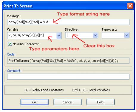
You can send multiple variables to a PrintToScreen. For example, if I understand what you are trying to do correctly, you could do this.


PrintToScreen("array%d]%d]%d] = %d ;", xi, yi, zi, array[xi][yi][zi] ); 

You can do this in the dialog box for PrintToScreen but it’s not obvious how, let me post a screenshot later. It’s easier to just use a line of user code.

Edit:
Here
[ATTACH]7300[/ATTACH]
printToScreen.jpg

Oh…wow, that will definitely help! Now the method you suggested only prints out 3 or 4 character per array value (2 or 3 numbers and a comma), whereas I could just stick with the method I am using now and Use one single PTS command. However, this prints out maybe 4 times as many characters per array value.
Does this mean it will in effect take 4 times as long? Or does each PTS command take about the same time, regardless of the number of characters being printed?

Yes, the EasyC Drag-and-drop to build the PTS Function only allows one Variable, but the Back-End Function ( most likely a sprintf() ) will handle many Variables. You can create a Test by using the User Code Drag-and-Drop and hand create the PTS Function with multiple Variables to test this… ( I would try, but my Cortex is at home )

This is where an Additional Dimension to the Array would be helpful…

Moderately more complicated than what you currently have…

I see that the End User, needs to Capture the Output from the PTS statements in the Terminal Window, Copy them to the Clipboard, and Paste them Into an Editor ( e.g. Wordpad, Nano, … ) save them as “Recording1.h”, “Recording2.h”, “Recording3.h”, … into the Directory with the rest of the EasyC Code.

Using a Binary Data Stream, you would need to Install a program like TeraTerm ( or equivalent on Linux or Mac ), start the Program and start a Binary Capture, then Run you Cortex Program, after its done, Close the Binary Capture, start a Program on the PC that Reads the Binary Captured Data and Writes the “Recording1.h”, “Recording2.h”, “Recording3.h”, … into the Directory with the rest of the EasyC Code.

They would need to download and Install a Terminal Program that can do a Binary Capture, and the Conversion Program, which you could Pre-Compile for DOS/Windows, Intel Linux and Mac versions, plus provide the Source Code.

Your Example Data is all less that 8 Bits per number. So an Unsigned Char could hold any of your Numbers.

Using the reduced output I mentioned in Post # 54, your ASCII Text Would look like:


0]10;
1]3;
2]5;
3]2;


That is 6 Bytes for the first line and 5 Bytes for each of the next Three Lines… A Total of 21 Bytes.

If the Array Number was sent as a 16 Bit Unsigned Integer and the Data as an 8 Bit Unsigned Character, each line would be reduced to 3 Bytes, Times 4 Lines, for a total of 12 Bytes, about Half the Data. If there is Half the Data, it can be sent in Half the Time, or Twice as much Data can be sent in the Same Time period.

I think that with Clear and Concise documentation, ( and a Nice You Tube Video A picture is worth a 1000 Words, as they say ] ) would make it easy enough for a Technically Minded person to setup and use…

You can think of larger Multi-Dimensional Arrays as Arrays of Arrays…

Here is a One Dimensional Array, of a Two Dimensional Array ( I think I got my Brackets right :wink: ):


int large_array[3][3][3] = { 
                            {
                                {  1,  2,  3 },
                                {  4,  5,  6 },
                                {  7,  8,  9 }
                            },                                                                
                            {
                                {  2,  4,  6 },
                                {  8, 10, 12 },
                                { 14, 16, 18 }
                            },                                                                                            
                            {
                                {  3,  6,  9 },
                                { 12, 15, 18 },
                                { 21, 24, 27 }
                            }
                           };


A good Use of a Four Dimensional Array, would be a One Dimension Array, of 3 Dimensional Coordinates.

The EasyC Functions are Compiled into the EasyC Library that is Linked into your Compiled EasyC Code, and can not be changed, ( without the Source Code ).

Use EasyC’s “User Code” Drag-and-Drop to Make you own variation to the PTS Routine…