Team 24C Super Sonic Sparks 2011-2012 Gateway Robot Reveal

Hello VEX Forum Community!

So for the past few days I’ve been thinking “Gee, I really should post my design process thus-far onto the VEX Forum.”, and today I’m finally getting to it.

First of all we’ve got a competition coming up (it’s tomorrow, actually) and our team was invited to the 2011 EMC Conference in Las Vegas last month, so we didn’t have a whole lot of time to work on designing and especially building. So, we had to decide on a design pretty quickly, and this was the first one we had that looked promising.

Anyway, onto the thing you all want to see; the pictures. Well, here they are: (Feel free to try clicking the pictures which I posted on Flikr, to get a much better look.)

[ATTACH]4246[/ATTACH]
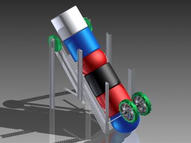
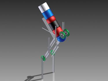
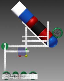
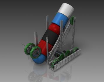
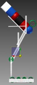
Starting off with our initial design concept, which was very rough, but seemed promising.

[ATTACH]4249[/ATTACH]
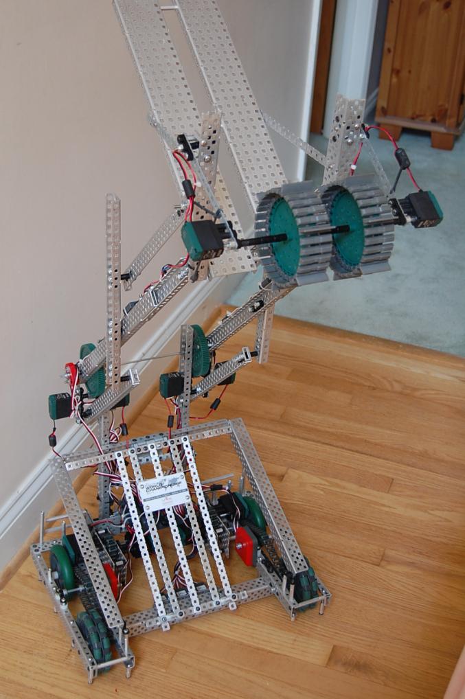
The basic idea was to have an “AURA-style” (seen on their College Round Up robot featured in this thread) 7-bar linkage to raise an angled platform with pivoting wheels/rollers on the front, which would spin to pick up the objects, loading them up the hopper.

[/ATTACH]
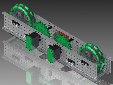
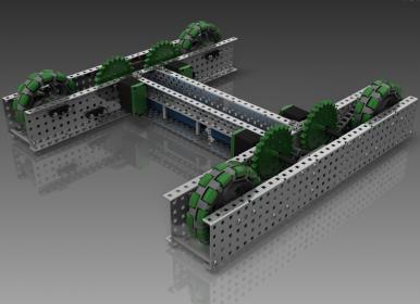
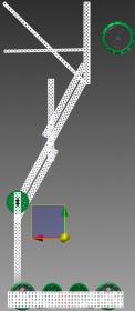
We also had an idea for a drivetrain, and designed half of it in CAD.

[/ATTACH]
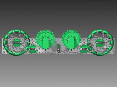
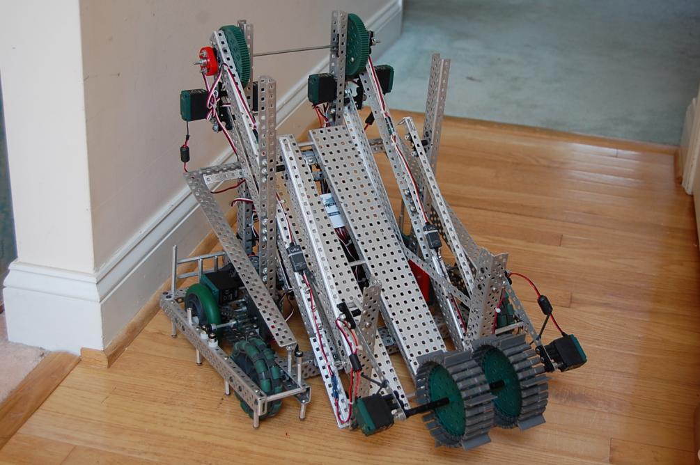
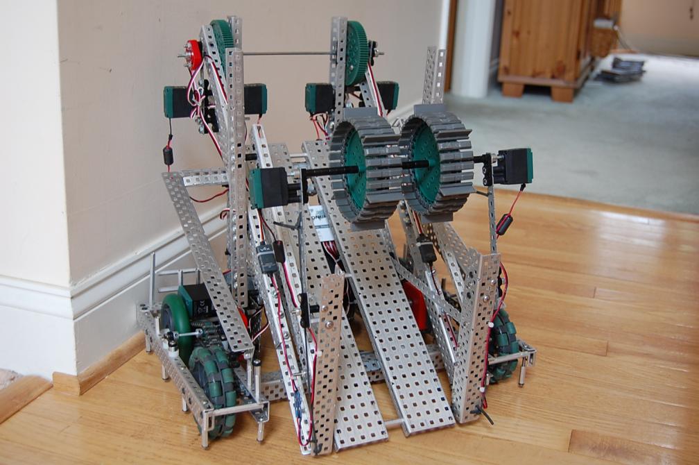
Here’s a better view of the chain run, which was taken by removing the back panel. The gear ratio is a 1:2 (geared up for speed), powered by four 2-Wire 393 Motors.

[/ATTACH]
Finally, the pretty picture of the final drivetrain assembly. The two batteries are placed in the very center, and low to the ground, as you can see.

~Jordan
VEX CAD Gateway Scorer Idea1.jpg
VEX CAD Gateway Scorer Idea4.jpg
VEX CAD Gateway Drivetrain Half2.jpg
VEX CAD Gateway Drivetrain Half1.jpg
VEX CAD Gateway Drivetrain5.jpg

I love the drive train. Very simple and elegant.

As I mentioned in another thread, your 4 bar idea is similar to my team’s. However, I am wondering if the objects will maintain their orientation for your design. We have a slightly different way of going about it.

Overall though, I think the winning design this year will be fairly similar to what you have here (and what my team has in CAD :D). Great job.

[/ATTACH]
After I finished the drivetrain, I attached the (still) unfinished mechanism to it, so see how it would look, and see how much it would weigh, the Center of Gravity, all that fun stuff.

[/ATTACH]
Center of Gravity with the arm fully raised, with 6 game objects.

[/ATTACH]
Center of Gravity with the arm fully raised, without any game objects.

[/ATTACH]
Center of Gravity with the arm fully extended, with 6 game objects.

[/ATTACH]
Finally I finished my VEX CAD Gateway field and was able to place my robot on it and see how it would look.

I hope you enjoyed this, and please feel free to leave questions or comments!
Thank you! :slight_smile:
~Jordan
VEX CAD Gateway Field Testing1.jpg
VEX CAD Gateway Full Robot3.jpg
VEX CAD Gateway Full Robot7.jpg
VEX CAD Gateway Full Robot1.jpg
VEX CAD Gateway Full Robot2.jpg

Very nice design and I like the drivetrain idea. Will the manipulator be able to load the barrels in all orientations, such as on their side?

It all looks very nice :slight_smile: I especially like the drive base. Sturdy and simple.

If I might ask, how much of this robot will be aluminum and how much will be steel?

Thanks for the compliments!

I’m not worried at all about the objects maintaining their orientation, it was just easiest to place them in the robot that way in CAD, haha. :stuck_out_tongue:

Glad you enjoyed it, and thank again. :slight_smile:
~Jordan

Thanks! And it sure will. I might add that it does, from what we tested. (We did build the manipulator, and pictures of that are being posted very soon.)

~Jordan

Thank you. :slight_smile:

Right now we’re planning on 99% aluminum, but if we encounter some tipping issues and think we need more weight down low we may swap the drivetrain C-Channel to steel.

~Jordan

Now onto the photos of the actual robot, in real life. First of all since we didn’t have much time to build this, we scrapped building the drivetrain, and instead simply used the old 24A drivetrain, which had the same general specs of our drivetrain we were going to build anyway. (Four 393 Motor drive, geared up 1:2 with 4" wheels.)

Here are all the pictures I have of the robot, which I took the past few days while it’s been at my house:

[ATTACH]4300[/ATTACH]
With the 7-bar raised all the way. (Yes, it reaches to 30".)

[ATTACH]4303[/ATTACH]
With the 7-bar down.

[ATTACH]4306[/ATTACH]
Showing how the robot will start at the beginning of the match, fitting inside the 18"x18"x18" size limitation. (just barely)

Enjoy, comment, ask questions! :slight_smile:
~Jordan
DSC_0067.jpg
DSC_0068.jpg
DSC_0077.jpg

I like the intake rollers. Our first prototype was somewhat similar and could “grab” the game pieces with ease. Your’s is a bit different that it grabs it at an angle. How does it perform?

Planning on programming it to go slower when the arm is fully raised?

Does the chain slip at all on the drive train? About three weeks ago I tried a drive train with a similar amount of contact on the drive sprockets but it slipped really easily.

Also VERY nice CAD, the rendering is awesome. I haven’t seen any teams (at least not this early) post their robot on a field and display it.

It was working pretty well for the one minute we got to test it, haha. :stuck_out_tongue:

Haha, oh yeah, we are. :wink:

Which drivetrain? I’m assuming you mean the one in CAD, but it hasn’t been built yet. I was pretty worried about the chain slipping, and decided that if it did I could always mount the Encoder (in the middle) higher. Unfortunately it would make it uglier, but oh well, if we end up having to. :stuck_out_tongue:

Thank you!

And I thank everyone for all the questions and comments!
~Jordan

Interesting idea. I like how you reduced the lifted weight, and I admire the H-drive. I’m not entirely sure about the center of gravity (over 18"), though… might want to toss some extra weight down low.

While our team feels capacity (3-5) is important, we didn’t want to lift our entire capacity above the goals like you are and are pursuing something that sets it up so the highest game piece is the one about to be scored. It causes less COG worries while keeping the same capacity potential (we think). Of course, we’re in the pretty early phases of this, so we’ll see how it turns out.

Thanks for the compliments! And believe me, the Center of Gravity was scary to see. I am planning to swap out the C-Channel in the drivetrain to steel vs aluminum, to add weight. Also the robot we have now can only actually hold ~4, maybe 5 game objects, so it isn’t quite as much weight up top. The drivetrain we have currently is a lot shorter, and would be much more prone to tipping, so we’ll have to see how it goes, and decide from there perhaps what to do with the new drivetrain, which is pretty well maxed out.

I like your idea of keeping the game objects as low as possible. I could end up changing the angle of the plate, just not too much to mess with the objects’ ability to slide down it easily.

~Jordan

P.S. I am now perpetually scared after seeing your Location.

Hey S^3, GREAT design. The graduated seniors o f REX 1727 have all joined up to make an all senior team. We’re all looking forward to seeing you all there (not to mention we think your robot will be our greatest competition!!!).

Man, us New Zealanders go to sleep for a night, wake up and then there’s all this on the forums! Looks soooooooooooo awesome!

Just a couple of things that we found out with our 6-bar (or 7-bar) arm that might help:

The center of gravity issues were usually only a problem when the arm was raised to maximum height (as you have shown in your diagrams) - three possible solutions that we thought of:

  1. Use steel on the base and aluminium at the top to lower the COG (I think you already said this), but the downside is the robot is heavier and thus slower. Also we never purchased any steel :stuck_out_tongue:
  2. Put more weight on the front of the drivetrain - maybe mount your batteries next to the front wheels on each side! Gives it more grip as well. Keeping the plates on the sides of the drivetrain low helps.
  3. (Easiest solution, and probably the best one): Most of the time you shouldn’t need to have the arm at maximum height - we used presets for our arm heights based on the potentiometer at the joint, so we could be sure that we weren’t raising the arm any higher than we needed to. You could make presets for the different goal heights (handy to have a second driver in this case). You’re unlikely to need to worry about it tipping forwards, only backwards.
    Since it should only be at maximum height when it’s at a 30" goal, it’s unlikely to be tipped by another robot. I would advise that when you’re backing away from that goal, back away slowly first, then start lowering the arm as soon as you can to a safe height, and then continue reversing at normal speed. This is how we did it for our autonomous after we watched the robot fall over backwards about six times. It requires a bit more driver practice and skill - most of the time people are used to just reversing away and then lowering the arm, rather than at the same time.

Personally (other members of our team would disagree), I would say that for that long axle that you’re using to power the lift might be a bit better if you made it two shorter axles on each side, and controlled the motors on each side separately (put a pot on the other side too). This helps prevent twisted axles, and also allows you to control each side of the arm separately in case one side skips or goes out of sync (you’ll quickly find that the longer the arm, the more force is required to lift it to a certain height because the force is acting further away from the pivot point, which encourages the gears to skip a little if they’re not at the right ratios/getting enough power/torque/somephysicsyterm). It’ll be helpful to write some code that checks that the two pots are roughly in sync as well (be careful though, the pots are unlikely to be returning similar values to each other).

When we saw that high school teams would get a 30" goal for gateway we figured that our 6/7-bar might be a pretty simple way of achieving that height! Cool to see that other teams are using it too :smiley: If you have any questions that you want to ask us (we probably don’t know that much more than you guys, but we might be able to save you some trouble with diagnosing issues etc.), feel free to pm or e-mail the address below (or even better yet, post below so everyone can see it)! Keep in mind we’re in NZ so… time zones.

Awesome design. I really like the intake, and seven bar. The drive-train is beautiful, i’m a sucker for good looking drive-trains;]. Can’t wait to see it compete! Good luck!

-Dave

Depends on each robot’s Centre of Gravity. It was true for ours, and probably for this one too judging by the CoG diagrams. By the way, are those diagrams from accurate weights for every part, or is it an approximation? I’ve never seen that actually done properly in CAD.
I’d say everyone reaching 30" is likely to have some problems with tipping this year. It took our drivers a few goes to stop flooring it before the arm was at a more stable height :wink:
It will be interesting to see what other solutions people come up with this season.

That’s a great idea/design! Hopefully It works well in competition! Good luck!!

hahaha
this is the new gateway “needle” design :wink:
now we just need an appropriate name for it!
cant believe how identical it looks like MY cad
i guess now we’re forced to upp it :stuck_out_tongue:
thanks for publishing the design and hope you will get vids of your first competition of the year! :slight_smile:
good luck!

We call it a ‘ramp intake’, with variations depending on the actual intake such as roller ramp intake, tank tread ramp intake, etc. etc. Dunno what anyone else calls it?