I’m going to explain a little more about the V5 battery in this topic and specifically what information the battery medic diagnostic tool is showing. We have released some reference material on the V5 battery in the past, but never discussed in detail what some of the terms actually mean.
An explanation of the battery led display is here.
and the steps for running the battery diagnostic tool here.
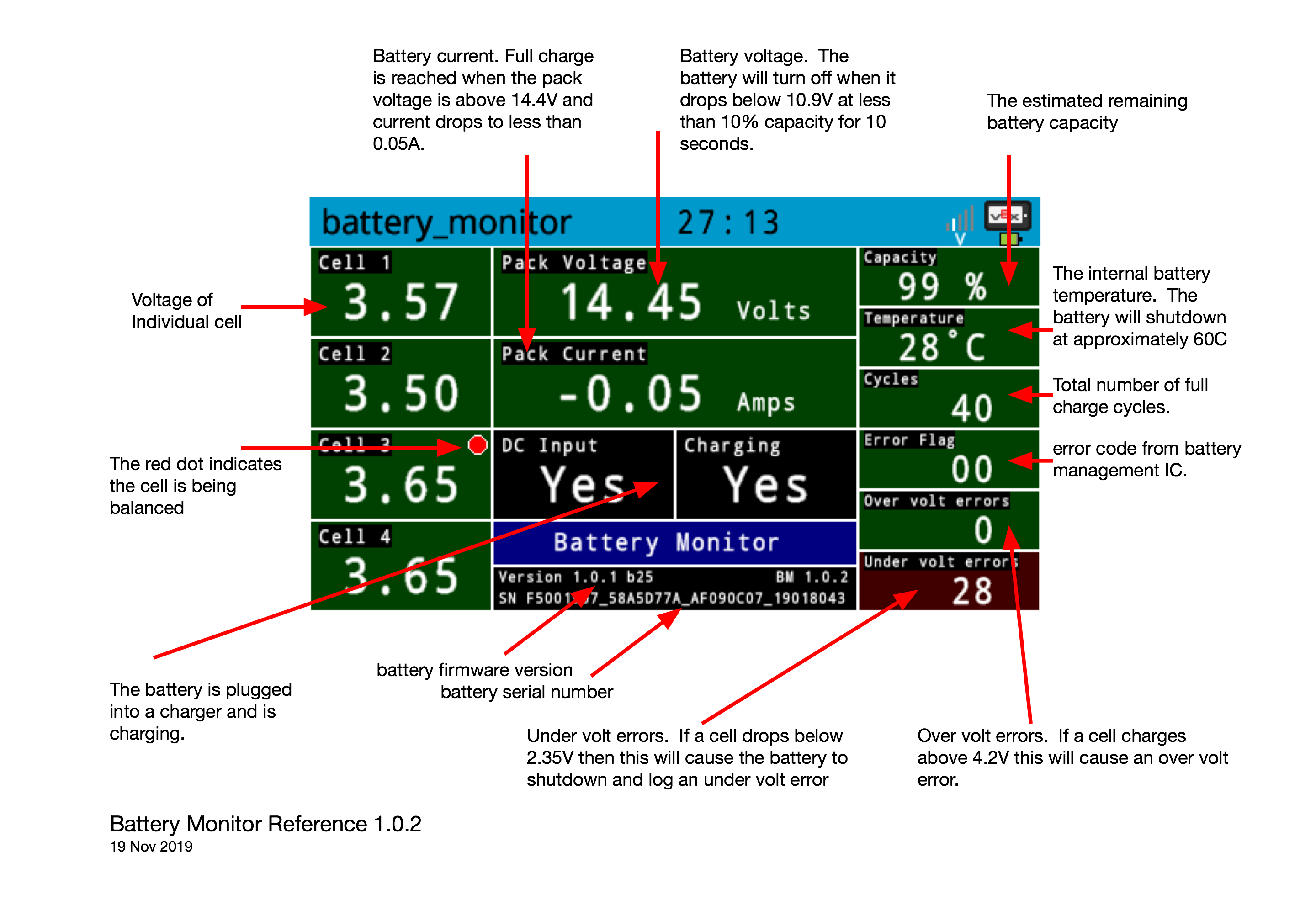
The battery monitor shows some detailed information about the internal state of the battery pack. The pack voltage and the current being supplied (or accepted when charging) is shown front and center. Individual cell voltages are shown on the left and battery state and errors over to the right.
The battery comprises four Lithium Iron Phosphate ( LiFePO4 ) cells arranged in series to give a nominal pack voltage of 12.8 volts. When charging, the pack voltage will reach 14.4V with each individual cell reaching approximately 3.6 volts. If a cell rises above 3.7 volts its background will be shown in red in the battery monitor program, this is still a safe voltage but shows that the cell may be charging quicker than others. A cell voltage of 4.2 volts will trigger an over voltage error and charging will be aborted, this is the highest voltage that we consider safe for an individual cell and will usually happen if other cells are not charging sufficiently to trigger an end of charge condition. The battery control system will terminate charging when the pack reaches 14.4V and charge current has dropped to below 50mA, this is handled primarily by hardware in dedicated circuitry. If this condition is not reached within 3 hours, charging is also terminated and we show an error code on the leds. (see first link above).
Towards the end of a charge cycle you may notice a small red circle appear in the battery monitor program near the cell voltage display. This indicates that the cell is being balanced, charge current is being reduced for that particular cell in order to balance the state of charge of all cells in the pack. This is normal and expected operation.
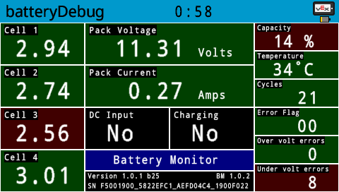
Over volt errors are fairly rare and will often stop occurring after several full charge/discharge cycles as the battery manages to balance the cells. More common are under volt errors, these will be seen during battery discharge if an individual cell drops below 2.35 volts, the battery will turn off the output and flash the red led quickly. Here is another screen shot with one cell close to under volt shutdown.
LiFePO4 cells have a fairly flat discharge curve, that means that their voltage remains stable most of the time they are discharging (at a fixed discharge current). However, when fully charged their voltage will drop quickly during the first few seconds of operation and also when they are almost depleted. Here’s a graph showing pack and cell voltage for a V5 battery being discharged at approximately 4.7A. ( see note 1 below regarding current )
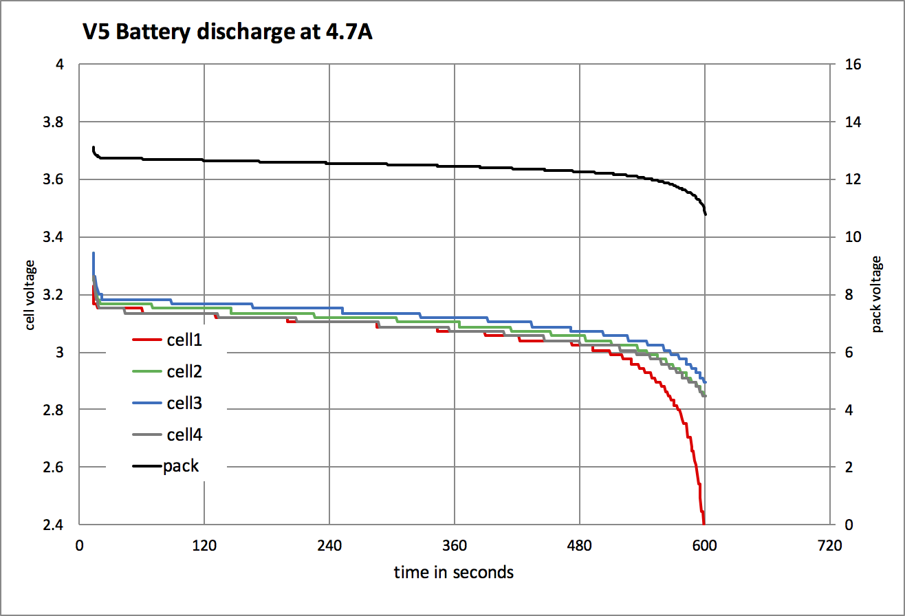
The cell voltage is shown on the the left hand side Y axis, the pack voltage is on the right hand Y axis and the discharge time in seconds is along the X axis. Notice that the 4 cells have pretty much the same voltage for most of the test duration, only near the end does cell1 (red graph line) drop quickly, it reached 2.35V and the battery turned off terminating the test. Even though this caused a shutdown and under volt error, the majority of the batteries energy had been used up. If all cells were perfectly balanced, the battery would have first indicated low capacity when it fell below 10% with a pack voltage below 10.9 volts. If that condition had persisted for more than 10 seconds the battery would also have turned off the output as all its energy had been used.
We show a few other fields in the battery monitor. cycle count is the equivalent number of full charge/discharge cycles, this gives an indication of battery age. Battery temperature is shown, this will typically be in the 20 to 40 deg C range. If battery temperature reaches approximately 60 deg C, it will turn off until the temperature drops. The error flags come directly from some of the battery management circuitry and would indicate such rare events as over current or over voltage protection In nearly all cases the battery will enter a safe condition which may take a few minutes to clear.
Note 1.
battery current vs motor current ( discussing stalled motors for simplicity )
It’s well known that V5 motors are limited to a maximum continuous current of 2.5A, however, 2.5A at the motor does not mean that battery current will be 2.5A. To achieve the 2.5A limit at the motor when stalled the voltage has been dropped, the exact numbers get a little complicated but to simplify things lets assume it’s set at 6 volts, this puts the electrical input power to the motor at 15W. The battery at nominal voltage of 12.8 volts when providing 15W of power would be supplying an average of 1.2A of current. Again these are example numbers, reality is a little different. My discharge test was approximately the same as running 4 motors at maximum current or more realistically 8 motors at more typical usage of a competition robot.