Last Year I worked on a Holonomic Drive (X-Drive). Sadly we had Trouble making a Consistent Autonomous. I recently happened upon Odometry and I Thought this could be the Answer.
(Traditional Odometry Wheel)
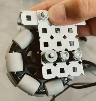
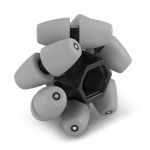
If my team was to ever build Holonomic Drive again: what would be the most Efficient design? I have seen many odometry systems with Omni-Wheels but I also wish to track sideways motion. This lead me to the 2" Mecanum Wheels.
(2" Mecanum)
From what I’ve experienced from holomic drives including mecanum is that they are not predictable in how they operate and rely on sensors (like odometry) to make them a viable solution in the first place. Using holomonic sensing would seem counter productive given this, but I’ve not tried it.
Mecanum wheels spin (slowly) if you push them sideways. So lets say you had a program that uses a calculation for distance going forward. Then changes when you want to go sideways.
My advice is to follow the gold standard of using two tracking wheels, one parallel to drive and one perpendicular alongside an inertial sensor. To save space (mostly just height) you can double stack two inch omni wheels. You can also attempt to not use the perpendicular wheel with traction wheels, however horizontal drift may still occur and be undetected.
In your experience do Mecanum Wheels Stutter when going sideways? Or have inconsistent speeds? What Mecanum wheels have you tested? I have not yet worked with the new 2" Mecanum wheels (our program recently ordered them so I should be able to run some tests soon), but I have worked with the larger sizes. Through my experience with the larger sizes I haven’t had any issues with consistency or accuracy.
Thank you for your answer. But do you have any reasoning for not attempting the Mecanum Odometry wheel?
In theory it should save Weight and Cost (rotation sensors are pretty expensive). In a standard X-Drive Odometry system you would have 2 Omni wheels and 2 Rotation Sensors (One for the X-Axis one for the Y-Axis). In the Mecanum theory you only have one Wheel and one Rotation Sensor. (also I am ignoring diagonal movement).
Visually there is more juddering from the robot for sure particularly during turns.
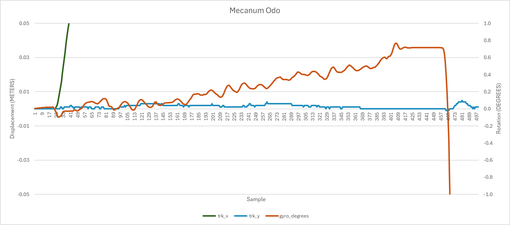
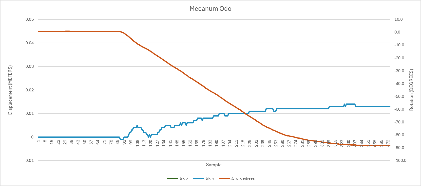
Now does that translate to detectable motion artifacts? Here were some readings - admittedly I don’t have these for regular wheels to compare. First graph is driving straight forward for 1m (positive x is field north, positive y is field east and heading is 0 deg north). At least there is negligible y displacement, but you can see the gyro picking up a distinct swing motion.
So at least on a straight trajectory this setup seems to do a reasonable job of mechanically cancelling any non-linearities between the wheels.
Rotation is a different story though. Below is what happens when the robot subsequently turns to the left by 90deg. x is too large to display here, but we drift east by about 1cm. Running several full turns you can easily see the robot drift quickly off its start location.
This was taken with 4" mecanum (note the gray PRO ones, so not VRC legal that i know of). I only have the older 2" mecanum - did not run tracking on those.
So the question is going to be can you come up with a calibration scheme to characterize strictly forward and sideways motion.
The issue is with one Mecanum wheel, you can’t tell whether your robot is moving sideways or forward, so your odometry won’t work very reliably. If you want to use just one wheel, it’d be better to use a single omni wheel tracker parallel to your robot—you lose sideways tracking, but you won’t have issues with sideways movement affecting your forward motion readings. Theoretically, if you wanted to use only one wheel while keeping the ability to track sideways motion, you could try to make an odometry pod similar to a caster wheel: you would need just one traction wheel, and two rotation sensors. I don’t know whether this would be an actual save in terms of space/weight though, given the extra material you would need for mounting. Another option would be to have two Mecanum wheels that are parallel to each other, with the rollers facing opposite directions: this might save space depending on your robot’s layout.
boolean = a Variable that either equals True or False
trackingWheelSideways = a Toggleable (by boolean) function that will change the distance calculation if True (if False regular calculation would be used)
moveDrivetrainSideways = a function that moves X-Drive Sideways
moveDrivetrainForward = a function that moves X-Drive Forwards
drivetrain = a Variable that is changed depending on which direction X-Drive moves
So are you saying that going forward worked generally well, but turning introduced drift? I may be misinterpreting (sorry if I am). What is the level of drift going sideways compared to forward? And do you think it would be viable to use a mecanum wheel as an Odometry Wheel (for Sideways and Forward motion. Excluding turning).
@BananaPi
But after we figure it out (and it works), wouldn’t that remove the difficulty (after posting the findings and how to do such things) for the future?
I don’t know, it probably could work decently, but will it be consistient?
If you have time for it, I would definatly figure it out. However, I would make sure you doing sacrifice other parts of your robot for figuring out this odometry.
I don’t have a capture for that saved right now. Would need to go run that.
I think the challenges you’ll face in general:
You want odometry to counter the unpredictable nature of a drivetrain. You’ll find that even on a standard drive there’s a tendancy for the robot to pull one way or another or rotate slightly particularly when accelerating. For example PID by itself is not a constant control mechanism - it is continually searching for the setpoint introducing slight variations in speed. Turns are even more unpredictable as you are relying on wheels slipping which will vary with COG, surface, speed, etc. Then there is what happens when you brush against the field perimeter or come in contact with a game element.
So if this is what you’re trying to correct in the first place, then starting with something that inherently couples motion in different directions and requires adding special case assumptions just seems like a hard sell to me.
Net, I would go with the tried and tested methods. Even these need a lot of development time to get to work reliably (and don’t underestimate this).
This topic is very complex and is hard to answer. Your replies have been very helpful.
The Mecanum wheels may be slightly inconsistent (Note: @NixRobots was very helpful with this, but the data was collected from a Mecanum drivetrain, in which, to go sideways, the wheels must “fight” against each other—for lack of a better word. This is compared to a single Mecanum tracking wheel, which I assume would be smoother.), but I think that it would be worth testing.
If it were to work, it should save a lot of space and money.
The VEX order of parts should come soon, and I will test the viability of the 2" Mecanums.
TL;DR:
I will be testing the 2" Mecanum wheels for odometry and will post the findings.
Thank you, everyone, for your help. If there is any additional info that you think would be helpful for testing it (coding, structure, etc.), or specific details you would like to know from testing, let me know in a reply.
This system is designed for autonomous skills, right?
Under driver control and with other robots, it won’t be accurate enough during matches if you need it for something.
In the match autonomous, 15 seconds is short enough that motor encoders are good enough.