We are attempting to use two potentiometers, one on each arm of our robot, and synchronize the movement of the arms through software (RobotC). Our code was written based on an assumption that we would get identical (or very close) values back from two potentiometers. However, we are seeing wildly different values when reading the potentiometers as we raise the arms. For example, when both start at zero, raising the arms by hand might give us values of 800 and 600, or 1200 and 800. (We are reading the potentiometer values, and just writing them out to an LCD.) We were hoping to correct this by using a ratio, but the values do not seem to follow any pattern.
This is the first time we have tried to use potentiometers. Can anyone tell me if values from two potentiometers should be consistent?
At this point, we are probably going to use encoders, even though we are only attempting to measure a rotation of less than 180 degrees - which would seem more appropriate for potentiometers.
Potentiometers can return a value from 0 to 4095 in Robot C If I remember correctly. There is no guarantee they will read the same in the configuration you mentioned but you might be able to get them closer than you report. Last year we put 2 on our arm one on either side but for backup not for synchronizing. so if one failed the other was already in place and ready to be used. our too were aligned so they both were about zero at one of the limits, they were within a 100 or so of each other at the otehr end of motion (~ 110 degrees).
They are essentially inexpensive resistors, and matching them is hit and miss. We’ve used them for the last 4 years and only had one go really bad.
Most people prefer some sort of mechanical locking device to synchronize motors, but if that isn’t a good option for you Shaft Encoders might provide a better resolution, however they tend to need another sensor such as a limit switch (or two in your case maybe?) to allow you to reset to zero both encoders at a known setting (limit).
Can you plot out the values as you go from floor to high point and see if each pot is acting in a linear fashion?
You may want to plot out many points and reverse that into a function. Hopefully it’s a first order equation on both sides. Maybe they just differ in their slope on a first order equation and don’t stray too far. You could set up a measurement jig (a glorified piece of paper with specific measured angles marked) and take a bunch of measurements to establish a better set of data points to give a more accurate curve. Excel can do an OK job for you there.
Once you have each pot’s equation you can see where you actually are from the current pot reading on each side and then recalibrate the motor power left/right based upon how far off each side is from the desired position. Then you can get fancy and try to stop the slow down/catch up cycle you will induce! Maybe it’ll be granular enough to not bee too noticable.
However re-calibrating the potentiometers may be a wee bit difficult to do match day. Drift of the pot values has been known to happen and is usually an activity before every match for the various key positions. So you may want to keep that calibration piece of paper/cardboard handy.
Mechanical coupling can be far easier to implement in the long run but beyond the 12" shaft length it can be difficult to implement. Downside is you have a shaft (and typically a cross support) in the way right in the middle of the robot.
On a side note, the thought of using these for arm synchronization worries me ever so…
If one breaks, then the arm could tweak itself out of proportion (I saw this happen so much last year)
They are great devices obtaining position info for an entire arm, but this task may be better suited for the encoders. At least with encoders you know that the values are going to be very similar (granted, if your motors are running at the same speed :P) because of the measurement technique!
But that’s my 2 cents. On our lift, we chose encoders for this very task.
If you REALLY wanted to use potentiometers, you could write a function that, upon powering up, calculates the % error between the two, and uses an algorithm to compensate for it. (I’m just pulling this out of the air, it could be more complicated but you get the gist)
Thanks for all the comments. Yes, we are aware of the range of values for the potentiometers, and we chose a starting position at about 25% of the range. There doesn’t seem to be any mechanical problem with the arms on our robot, and no problems with the wires. I also understand the suggestion to mechanically link the arms, but in our configuration, that would not be easy.
It sounds like others have run into similar problems with the potentiometers. If they are not reliable, we don’t want to have to do any “work arounds”.
We will replace both potentiometers with encoders. And we already have a limit switch at the bottom of the travel, so we can use that to reset our encoder values.
My team has tried to use two pots on the arm in the past, one on each side, but we found that it only caused more problems than it was worth. The best solution is to mechanically lock the two sides and only use one pot. You may also want to look into encoders (either the integrated encoders or the quad encoders). They tend to me more reliable and don’t drift.
Pots should not drift. Seems like new experiments are needed, put two (or more) pots on a single axle and test to see if the values track. The absolute values will not be the same but the tracking error should be within 1 or 2 degrees I would think, a digital count difference of perhaps 30.
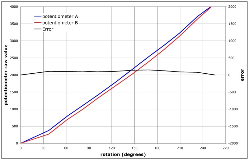
Did a quick test today, two pots on the same axle along with an encoder to measure angle. Potentiometer data was slightly filtered to remove noise. Here is a graph of the results. Useful range is probably about 200 degrees, maximum error within that range, after removing the fixed offset, was 36. That is, the error was +/- 36.
Thanks again for all the valuable information. We took off our potentiometers and found that one was definitely faulty - giving us bogus values. While we would prefer to use potentiometers, we didn’t have any replacements in stock. We did have an extra set of encoders, so we put those in instead. Onto the next issue …