So I am trying to upload data from a cortex to a computer and read it. I hooked the UART port up to a serial-USB converter and into my computer. I use tera term to read that data but all of the characters are wrong.
I tried doing this once and the only way I was able to get it to work was to connect the UART ports on two cortexes and have the second cortex communicate to the computer over USB. The ideal way, though, is to use a programming hardware kit and just print the data wirelessly over VexNET.
Which UART port? If you mean UART1 or UART2 next to the I2C port, then they are not compatible with a normal serial-USB converter, you need one that takes TTL (well, 3.3V really) levels. If you use a normal RS232-USB converter you will probably damage the cortex.
If indeed you used the correct type of serial-USB converter, the baud rate is probably wrong.
I have tried both UART 1 and 2 with the same result. I have also tried 2 different USB-serial converters one of which being the USB-serial part of the old vex programming kit. I don’t know if these are TTL or not.
How would I be risking damage to the cortex because I am only transmitting data, not recieving it on the cortex, so there should be no current comming into the UART port?
Well, if you only connected the output of the cortex you will probably be OK. RS232 can be +/- 15v, although more typically these days it is much less. Feed 15V into the cortex and it will probably be toast. If you are using the 9 pin D connector to USB then that part is RS22, if you have adapted the 6P6C connector (the RJ11 telephone style connector) from the old programming kit then that is TTL (by that I mean 0 and 5V levels).
Have you set baud rate the same at both ends (and also parity and stop bits, should be 8data, No parity, 1 stop I think).
Have you connected the ground (0V, black cable output) as well, you need two wires for output, ground and transmit signal.
I have set the baud rate on both ends to 9600.
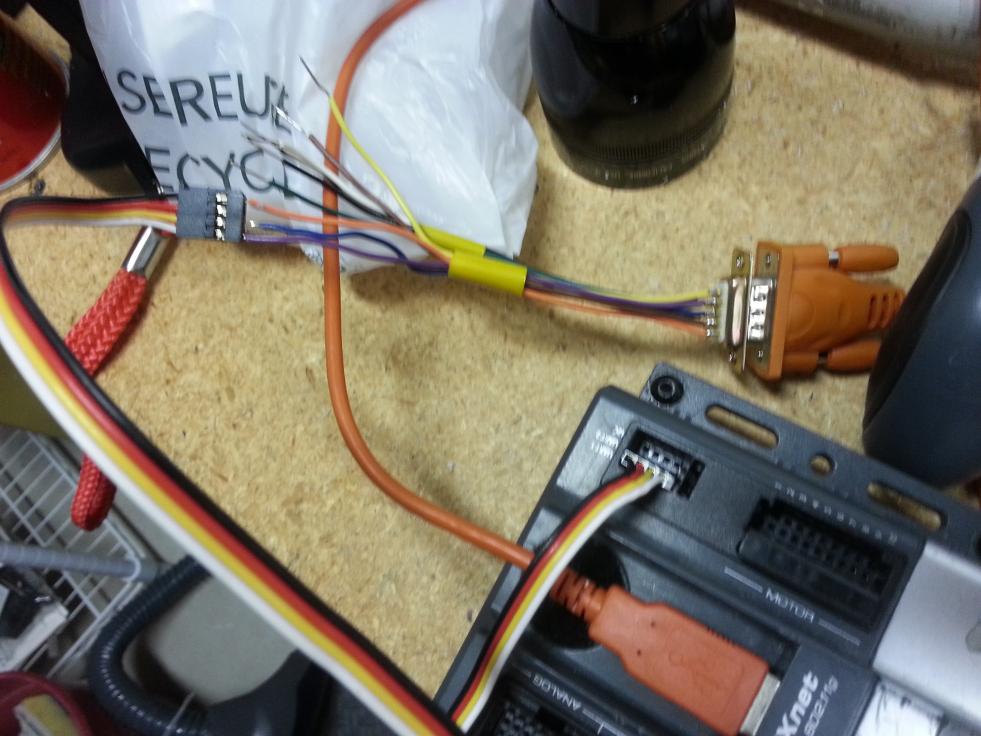
I connected Rx, Tx, and Ground from the UART port to the my serial cable (I will post a picure later today)
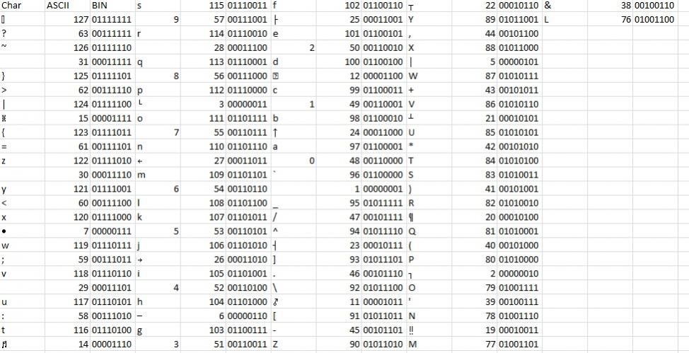
This is the data I got from printing all ascii characters
The voltages on the D9 connector are almost certainly outside the safe range for the Cortex serial port, as James points out. Not only are the voltage swings too large, they are also inverted (TTL serial uses non-inverted, and RS-232 serial uses inverted). This inversion is probably the reason you are getting gibberish. If you look at the table you posted, you can see it is receiving mostly 1’s at the beginning and ends up with mostly 0’s. It isn’t a perfect countdown because the start and stop bits are also inverted, which throws off the byte framing logic in the UART.
You must use a level shifter to get the signals into the proper voltage range and invert them.
Something like this SparkFun product would work nicely. Unfortunately the order of the pins on the 4-pin connector doesn’t perfectly match the VEX UART port, so you have to make a custom cable (or just re-arrange the pins on a standard Vex I2C cable).
For my Vex serial port work, I just made a dedicated cable using this. Works with VEX Cortex and VEXpro. For the VEX PIC controller, you should use this cable instead.
Thank you, I will try this in a few days. I had a second idea-because this is an inversion problem would just using NAND gates acting as NOT’s to inverse the Tx and Rx work? I am asking before I try this in case it could damage the cortex or my computer.
This would be a step in the right direction, but it still has all the same voltage range warnings we’ve been mentioning. I would never use a part rated for 0…5V on an interface spec’d to ±25V.
That being said, I don’t think using a NAND on the Cortex TX line would put the Cortex or the computer in any risk beyond what you are already taking. The NAND gate would be in the most risk since it has no protective circuitry like the Cortex.
I wouldn’t try this on the Cortex RX line since the NAND gate would almost certainly burn out, and it might pass bad voltages back to the Cortex.
Another option, would be to build something like this. These parts are pretty basic, and would cost about $8 at a Radio Shack.
So I bought the cable that you posted, but was wondering how to hook it up. I would hook RX-RX, TX-TX, and GRD-GRD, but would I hook power to power? I don’t think I should because then both the computer and robot would be putting power into each other.
connect GND to GND (black wire on cortex)
connect TX to RX (transmit on cortex goes to receive on PC/cable)
connect RX to TX
you may just have to guess on which is which.
Do not connect power (red wire on cortex).
If you have problems I can check later as I have that same cable.
According to the schematic, TX is orange and RX is yellow. The cortex UART pinout is here.
So the order of the pins to the Cortex should be:
[INDENT][LIST]
*]Black (gnd)
*]no contact (+5)
*]Orange (PC TX->Cortex RX)
*]Yellow (Cortex TX->PC RX)
[/LIST]
[/INDENT]
With the connecter key next to the yellow wire.
Thank you for all the help getting this to work. I am getting good data now. I have one problem with it. I sent 40,000 characters at 9600 baud and it took 58 seconds using the posted function. Why does this take 58 seconds when it should only take about 4 seconds?
void sendUARTString(TUARTs UARTport, string s)
{
	char buffer [15];//15 chars is the most that will be sent
	sprintf(buffer, s);
	for (int i=0; i<strlen(s); i++)
	{
		sendChar(UARTport,buffer*);
		while(!bXmitComplete(UART1))
		{//this makes RobotC not give a warning
		}
	}
}
Don’t forget that 9600 baud means 9600 bits per second. One character will have 8 bits + start bit + stop bit + parity (if enabled) so 9600 baud is approximately 960 characters per second.
40000/960 = 42 seconds.
So with all the other overhead (inefficiencies of sending 1 character at a time) 58 seconds is about right.
Edit:
So this is the code I used for transmission to the LCD in ROBOTC.
    // send to port
    for(i=0;i<22;i++)
        {
        // wait for transmit complete or timeout
        // Under normal circumstances this should not be needed, there is
        // a transmit buffer larger than most messages
        // timeout here is set at about 200uS (from experimentation)
        timeout = 0;
        while( !bXmitComplete(lcd->port) && (timeout < 20) )
            timeout++;

        // send char
        sendChar( lcd->port, lcd->txbuf* );
        }
bXmitComplete will return almost immediately until the internal ROBOTC buffer fills up.
With the LCD code, a message was only sent every 35mS so the buffer would never overflow. If you are hammering on the serial port you will spend a lot of time waiting for an empty buffer and may want to have a chunk of say 32 bytes followed by a few mS of delay. At 9600 baud, however, you will not be sending them any faster (probably) than you have already achieved. Ig you want faster transfer, increase the baud rate, I have successfully used speeds up to 230000 baud.*