Not to be judged but I thought odometry was a sensor.
A question I’ve been too lazy to ask, what is a PID used for besides autonomous stuff? I loosely know what PID is, but besides autonomous what’s it used for that the VEX motors don’t already handle? I’m a beginner so this stuff is all new to me.
Basically any electric task where you can overshoot can use pid such as heating
we listen and we don’t judge!!!
hello I like robotics and can help with anwsers
The Vex Motor encoders are typically a little off compared to using a tracking wheel. Tracking wheels use Free spining insert to spin the rotation Sensor more accurate then compared to Motor encoders.
In the past I’ve used a PID for my flywheel control. They’re helpful with keeping a motor at a consistent speed.
Far and away the biggest use of PIDs inside of VEX is to control for reaching a target position with the drivetrain, whether by driving linearly or turning angularly. PID control helps to reach the target as quickly as possible while minimizing overshoot/error. See this SIGBots Wiki article. It can also be used for other systems that need to reach a desired position, such as a lift. PID control can also be used to minimize error while maintaining a target velocity, for VEX most often seen in flywheel mechanisms, which the SIGBots Wiki also has an article about.
PID is used mainly for very precise tasks. If you have ever ridden an elevator you notice how the elevator always perfectly lines up with the floor. This is due to the PID programmed by whatever Schindler company (Schindlers list is a great movie). Anything from your path movement to a rotation of a motor can be very precise if PID is used.
Odometry is the concept of finding some way to figure out “where am I?”
Sometimes it is x, y, and a rotation. Other times it might be x, y, z, and a rotation (in 3D space there are different types of ways to do this).
The two contendors for odometry is visual and wheel-based. Oftentimes, you can “fuse” both to get the speedy and reactionary benefits of wheel odometry with the anchored benefits of vision based.
For Vision odometry, VEX Robotics created the GPS sensor: V5 GPS Sensor - VEX Robotics
Which was supposedly a “catch all” odometry solution to know where the robot is at all times. However, it has immense limitations in its tracking quality.
For example, in this post here: Is GPS a great tool for autonomous? - #5 by jpearman
Jpearman states that it refreshes 25 times per second. If the robot were turning at 100 times per second (for example with a 600 RPM on 3.25" wheels roughly), the robot would turn 24 degrees between each frame which is quite significant especially if you want to have a reactive PID.
You can see the GPS Sensor tracking vs real world movement in the comparision:
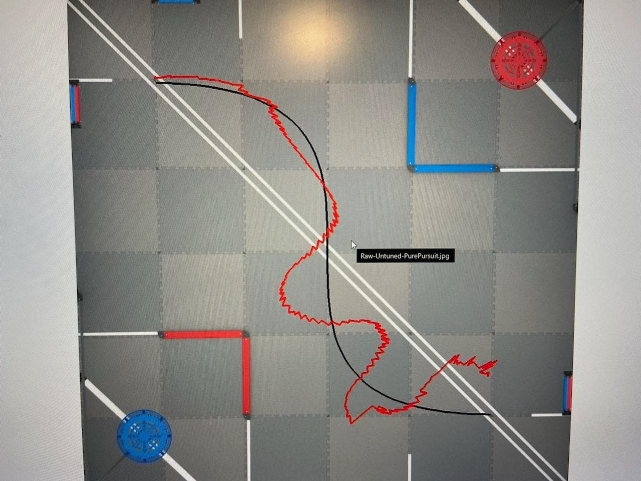
Source: Is GPS a great tool for autonomous? - #11 by Bubski
Also note that
Realisitcally speaking, in order to get high quality tracking, you’d need global shutter camera with extremely high compute power. I estimate paying around $3500 to get a vision solution to “match up” to wheel odometry’s as the robot is moving. I… have tried one with a $1300 solution, and for something like vision odometry you absolutely need a 98% $3500 solution or you might as well just use wheel-based odometry for autonomous.
For wheel-based odometry, I believe that 2 wheel + Inertial sensor is the best to establish odometry coordinates. It has the least amount of space for the highest possible accuracy. You can add more wheels for redundancy but it’s not necessary.
- It WAS almost entirely necessary to have 3 wheel odometry with V4/Cortex because the gyroscope VEX sold was not that good of quality, especially with drift. But the V5 inertial sensor is leaps better.
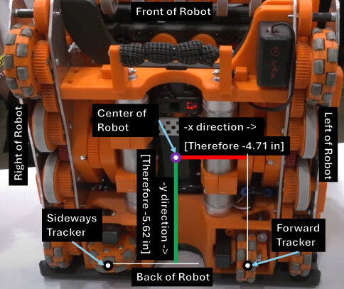
Here’s an example of WISCO’s odometry, a picture taken from a First Updates Now (FUN) interview:
PID is one of the most popular well-known algorithms in the industry to have more precise control of motion. The motion might be to make a motorized arm reach a specific angle or to make a flywheel spin at a consistent speed. It is used in a car’s cruise control and steer-by-wire system, air conditioners, nuclear reactors, electric dams, airplanes, your computer fans, rockets, boats, telescopes, camera gimbals, industrial ovens, etc. PID is used everywhere.
A good example of a PID algorithm is from the JAR-Template: JAR-Template/src/JAR-Template/PID.cpp at main · JacksonAreaRobotics/JAR-Template · GitHub
The VEX motor has its own embedded PID, but it is not recommended to tune the kp, ki, and kd constants in the motor because it’s not as maintained anymore. I encourage using just standard voltage to control the motors with your own custom PID. The main reason why you code your own PID is because you have more of a granular grasp on how you want the robot to do a turn. Sometimes, you might want to turn very snappy-like. Other times, you want the robot to turn slowly. But the biggest reason is that a custom tailored PID grossly outperforms default preset PID tuning parameters.
I have released a PID tutorial, but someone hijacked my YouTube. Currently recovering the YouTube channel so fingers crossed that the tutorial will be available again. Also note that if I cannot get it recovered, I might make another tutorial that follows more appropriate coding standards.
How can the same code on the same robot get different results in successive tries?
I can understand that the robot does not do the thing we intended to via code, because of build issues, so lets say, it drifts a little or it overshoots its distance. When you restart the program shouldnt the robot behave the same way again, since all the ineffencies are still the same.
How come, we get varying results in successive tries?
Are you using PID? If not then use PID as it is the best way to get repeatable autons
Woah! Do you mean degrees per second? In what situation would/could a robot be spinning at 100 revolutions per minute?? 
Hi Connor, as a relatively new to VEX-er myself I greatly appreciate your indepth and informative comment however I was wondering one thing, you have shown WISCO’s odometry setup and suggested that 2 wheel is the best but also referenced the VEX V5 intertial sensor’s capability to track drift very effectively, which, from my limited understanding the purpose of a horizontal odom wheel anyways, which is why I am confused whether by suggesting 2 wheels is the best for odom if you mean 2 vertical wheels parallel with the drive or 1 hori and 1 vert!
I used to think six wheels, no omni wheels all normal, with 4 motors was the best setup.
100 revolutions per minute*  Yeah that was my mistake. I should have proofread that more. That is 36000 degrees per minute.
If there is a camera update that is every 25ms, the result is 1/0.025 = 40 frames per second, or 2400 frames per minute.
36000/2400 = 15 degrees per frame.
That seems more accurate lol. But that is quite a lot worse compared to wheel odometry where the sensors can be as low as 5ms per reading.
I just provided this info more as a worse practical case, if you will find the robot spinning 100 rotations per minute in VEXU. 600 RPM 3.25” wheels with the motors given voltage at a horizontal and vertical distance of 15” between 4 wheels should yield around 100 RPM robot spin.
The biggest odometry drift now is not the IMU but rather the tracking wheels themselves if everything is done right. If you have calibrated your IMU’s scaling correctly, your tracking wheels will be whats causing most of the error in tracking. The omni wheels have bumps and inconsistencies with its outer profile as it spins and drifts across the field tiles.
how do you even use pid. 