Odometry is the concept of finding some way to figure out “where am I?”
Sometimes it is x, y, and a rotation. Other times it might be x, y, z, and a rotation (in 3D space there are different types of ways to do this).
The two contendors for odometry is visual and wheel-based. Oftentimes, you can “fuse” both to get the speedy and reactionary benefits of wheel odometry with the anchored benefits of vision based.
For Vision odometry, VEX Robotics created the GPS sensor: V5 GPS Sensor - VEX Robotics
Which was supposedly a “catch all” odometry solution to know where the robot is at all times. However, it has immense limitations in its tracking quality.
For example, in this post here: Is GPS a great tool for autonomous? - #5 by jpearman
Jpearman states that it refreshes 25 times per second. If the robot were turning at 100 times per second (for example with a 600 RPM on 3.25" wheels roughly), the robot would turn 24 degrees between each frame which is quite significant especially if you want to have a reactive PID.
You can see the GPS Sensor tracking vs real world movement in the comparision:
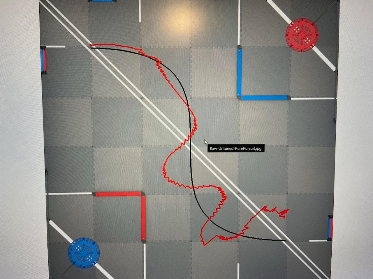
Source: Is GPS a great tool for autonomous? - #11 by Bubski
Also note that
Realisitcally speaking, in order to get high quality tracking, you’d need global shutter camera with extremely high compute power. I estimate paying around $3500 to get a vision solution to “match up” to wheel odometry’s as the robot is moving. I… have tried one with a $1300 solution, and for something like vision odometry you absolutely need a 98% $3500 solution or you might as well just use wheel-based odometry for autonomous.
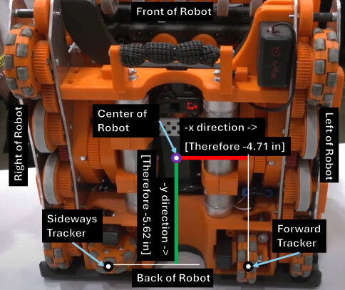
For wheel-based odometry, I believe that 2 wheel + Inertial sensor is the best to establish odometry coordinates. It has the least amount of space for the highest possible accuracy. You can add more wheels for redundancy but it’s not necessary.
- It WAS almost entirely necessary to have 3 wheel odometry with V4/Cortex because the gyroscope VEX sold was not that good of quality, especially with drift. But the V5 inertial sensor is leaps better.
Here’s an example of WISCO’s odometry, a picture taken from a First Updates Now (FUN) interview:
PID is one of the most popular well-known algorithms in the industry to have more precise control of motion. The motion might be to make a motorized arm reach a specific angle or to make a flywheel spin at a consistent speed. It is used in a car’s cruise control and steer-by-wire system, air conditioners, nuclear reactors, electric dams, airplanes, your computer fans, rockets, boats, telescopes, camera gimbals, industrial ovens, etc. PID is used everywhere.
A good example of a PID algorithm is from the JAR-Template: JAR-Template/src/JAR-Template/PID.cpp at main · JacksonAreaRobotics/JAR-Template · GitHub
The VEX motor has its own embedded PID, but it is not recommended to tune the kp, ki, and kd constants in the motor because it’s not as maintained anymore. I encourage using just standard voltage to control the motors with your own custom PID. The main reason why you code your own PID is because you have more of a granular grasp on how you want the robot to do a turn. Sometimes, you might want to turn very snappy-like. Other times, you want the robot to turn slowly. But the biggest reason is that a custom tailored PID grossly outperforms default preset PID tuning parameters.
I have released a PID tutorial, but someone hijacked my YouTube. Currently recovering the YouTube channel so fingers crossed that the tutorial will be available again. Also note that if I cannot get it recovered, I might make another tutorial that follows more appropriate coding standards.