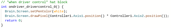
I want it to make it so that you can draw on the brain with your joysticks during driver control. What about this makes it not work, and how could I make it work? (error it gives is "too few arguments to function call, expected 2, have 1, highlighting one of the partentheses in red. When I remove it, it gives me a different error saying to put that parenthese back.)
The function draw pixel takes 2 parameters (x and y) and you are only giving it one. Replace the * with a comma. you may have to do some conversion from the joystick values to the brain pixel values.
As the error says, you only have one parameter. You are multiplying the two axis values together, turning them into one number. I would assume you meant to put a comma instead, which would make Axis1 the x coordinate and Axis2 the y coordinate.
Also, the 0,0 coordinate on the screen is the top-left corner, with positive y going down, so you may want to multiply axis2 by negative one for it to go the same direction as you are moving the joystick. You probably also don’t want the dot to be off screen 3/4 of the time, so I would add 100 or more to both the x and y coordinates to make the pixel always visible.
The drawPixel command requires two inputs - the x coordinate and the y coordinate - separated by a comma to determine where to draw the pixel. You could try something like this:
Brain.Screen.drawPixel(Controller1.Axis1.position(),Controller1.Axis2.position());
To be clear, I don’t know if this will perform the way you want it to, as I suspect the geometry for drawing on the brain (I assume in the manner of an Etch-a-Sketch?) will be more complicated, but this should read without errors.
You are multiplying the controller axis positions, instead of using a comma. I believe it should be:
Brain.Screen.drawPixel(Controller1.Axis1.position(), Controller1.Axis2.position());
whatever number i put, it only works on a portion of the screen. is there a way to make it work everywhere?
This actually works, but it only draws one one part of the brain. How can I make it draw all over the brain? Also it’s kind of slow, and it does dotted lines. I want to make it maybe like track joystick movement or something for research purposes.
Assuming your drawing code looks like this:
Brain.Screen.drawPixel(Controller1.Axis1.position(), Controller1.Axis2.position());
The red circle is the space on the screen it will draw on
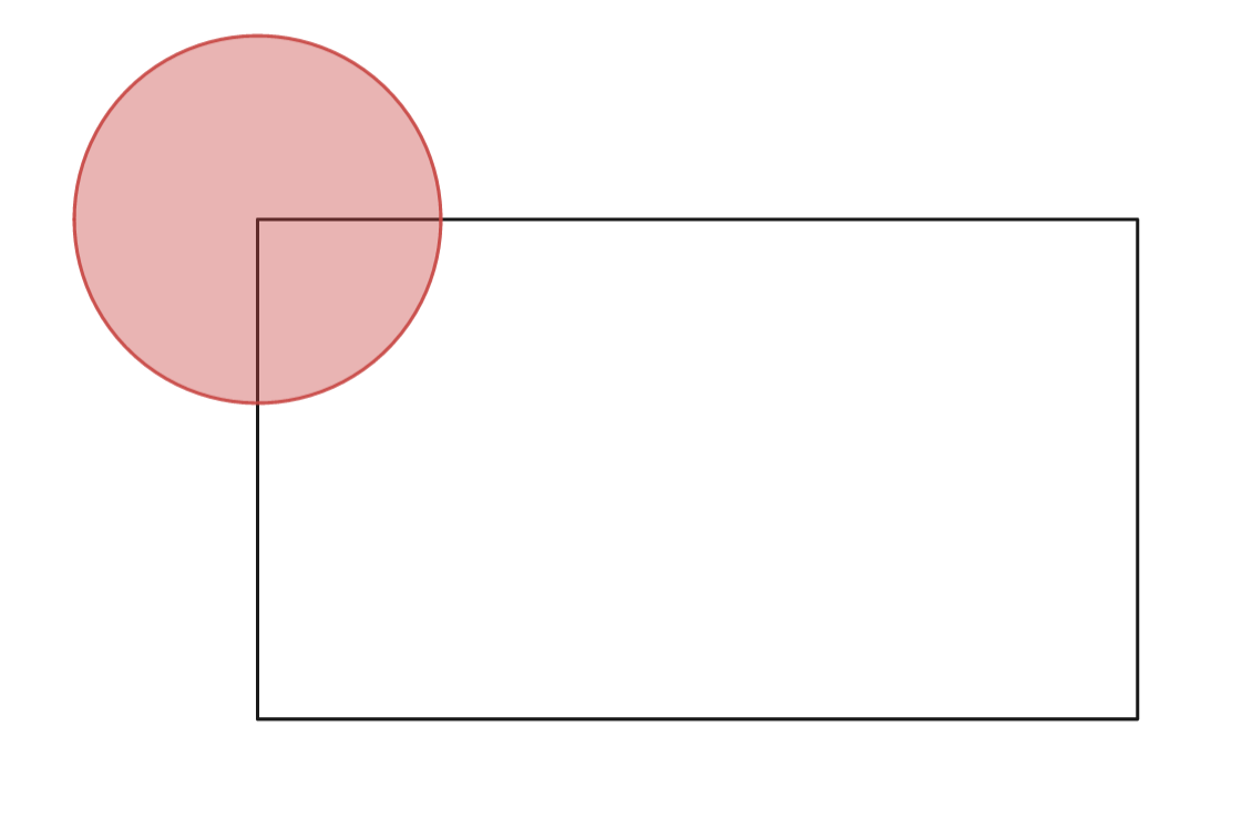
I’m assuming you want it to be fully on the screen, which you can do by adding half the width of the screen to x and half the height of the screen to y before drawing.
// This will center the circle on the screen
Brain.Screen.drawPixel(Controller1.Axis1.position() + 240, Controller1.Axis2.position() + 136);
Speed is based on how fast you run the loop, reduce the wait in your while loop to make it run faster
You need to clear the screen every loop so you aren’t drawing on top of what you drew before. Put Brain.Screen.clearScreen(); at the beginning of your loop to clear the screen.
Is there a way to make the circle cover the entire screen?

Multiply the joystick values by the amount you want it to be bigger by.
You need at least some wait, there is no point running it as fast as possible when most vex devices only update their values every 20 milliseconds.
Brain.Screen.drawPixel((Controller1.Axis3.position() * 2) + 240 ,(Controller1.Axis2.position() * 2) + 136);
So, how should i edit this? Is it good? It’s meant to make the circle cover twice the space, and make it in the middle. Not sure how to implement the wait or how much.
Yup, that should do what you want. To add a wait you can run wait(20, msec); at the end of your while loop, which will make it only process the stuff in the loop every 20 milliseconds (there are 1000 msec per second). I recommend doing 20 because this is the rate that most sensors update (to my knowledge), though some things are faster and slower.
Yep! 2 problems remain, however
Moving joystick vertically moves drawn line horizontally, and vice verse
Line is still dotted (understandable if can’t be fixed)
You could try swapping the order of the joystick values in your draw pixel code, as that should fix the problem with vertical joystick movement causing a horizontal line. To fix the dotted lines, you could implement a couple of variables as memory to connect each dot as it is made.
(this is assuming there is a “draw line from (start x, start y) to (end x, end y)” in text coding and not just blocks, which would be really weird, as it usually seems blocks is the one with missing functions.)
Example of both of these recommendations in one:
set (variable x2) = ((joystick axis 2 position) * 2) + 240
set (variable y2) = ((joystick axis 3 position) * 2) + 136
draw pixel (variable x2) , (variable y2) - not really needed because of this ![]()
draw line ((variable x1) , (variable y1)) to ((variable x2) , (variable y2)
set (variable x1) = (variable x2)
set (variable y1) = (variable y2)
This is not actually working code, merely a somewhat accurate logic model imitating what the code may look somewhat like. I will leave the actual code-building to those who know how to do it. Don’t change the order of the operations, though, as that would severely mess up the lines drawn and make the code not work.
You could keep track of where the joysticks were on the previous iteration of the loop and use drawLine to get rid of the dotted issues. As for the joysticks being reversed, make sure you are using the correct axis for your parameters.
I don’t know how to make or work variables…
Wouldn’t it make a square, because it can have a width of 200 and a height of 200?
Also, to make the drawing cover the entire screen, change the input of (((axis pos 2) * 2) + 240) to (((axis pos 2) * 2.395) +240) and change (((axis pos 3) * 2) + 136) to (((axis pos 3) * 1.195) + 120)
Yes, but the joystick doesn’t output a square because the joystick itself is a circle. (it’s not a super circular circle as you can see here)