Ray,
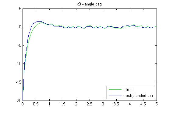
I decided to simulate the effect of the new Spark 2DOF imu (part SEN-00838)which uses ADXRS401 (±75 deg/s, 15mv/deg/s) and ADXL203 (+_1.7g, 1000v/g). This imu has much better scaling than the 6DOF but of course it trades max range. My simulation shows that the Vex bbot can only handle about a 20 deg init_tilt error and recover. I used this with both IMUs and although the 75 deg/s limit was reached and there was about a 5 deg tilt error for a short while, the bbot was able to recover. I think it would be fine for this robot. Without road noise, the max g Ive seen is about .4 g with the 20 deg initial tilt. Some day we will get a measure of the road noise g’s.
Attached are the tilt angle response plots of the true tilt vs the blended rate gyro/accel tilt (blending time constant = .5 seconds)
The high sensitivity of the ADXRS401 allows you to increase the blending time constant considerably because drift due to the A/D LS Bit 7.5 times smaller. So, probably 3 to 5 seconds would work provided you don’t hit the limits. The bbot could not recover with a 3 sec blending time constant for the 75 deg/s rate gyro once it saturated.
Thanks Chris. I tried to run the bbot in auto mode, with few changes you gave me and it didn’t make any difference. The bbot is still too sluggish to tilt. I looked at your video again, and I can see that your bbot even without the encoders, is more responsive. This makes me think that you may have made some code changes after you uploaded the code to this forum and before the video was filmed. Please confirm. From my previous experience, sluggishness could be result of wrong Kalman scale factor or any of the K filter constants may need adjusting. I will post my video later tonight, after youtube digests it. Thanks again Chris.
Not very impressive. I am not sure I understand what you mean by not being able to recover after more then 20 deg tilt. I think you don’t want the bbot to fall more then 20 deg, before it tries to recover. In fact it should try to balance instantly after tilt changes even the slightest (5 deg perhaps). If you wait more then 20 deg tilt, you have to do some heavy math to try to recover the bbot. I think what you are saying is that a 5DOF IMU is not sensitive enough to give a sufficient reading for the motors to be driven. I think my NXT uses a cheap $35 gyro from hitechnic.com, which I am sure is not very sensitive either, but the NXT balances really well. I gues I need to study this a bit more, but in the meantime could you tell me how to get better (quicker) response to tilt from the 5DOF IMU, as I can see in your second video. Thanks.
Ok, looked at your video…
First, you must initialize with the bot at complete rest to zero out the rate gyro bias for about 1 second. If it is moving when you turn it on, your tilt drift will be larger.
Second, you have built your robot with a higher center of gravity, a larger moment of inertia about the axle and a larger wheel radius than mine. Standard inverted pendulums (fixed center of rotation) have a natural frequency inversely proportional to the square root of the length divided by the radius of gyration (sqrt of moment of inertia divided by mass). If you have a point mass the radius of gyration is equal to the length so the frequency is inversely proportional to the sqrt of length. For the bbot , its more complicated due to other moving parts, but your “pendulum length” is larger than mine so it will respond slower. For the same tilt angle, you will also need more torque from the motors to balance because gravity is acting through a larger lever arm plus you have made it more difficult for the motors to supply this torque by using a larger radius wheel.
So to have a chance, you must increase the k_p and k_p_rate gains (tilt and tilt rate) , probably by a factor of two but you must experiment. It would probably be better to wait until you get your encoders to start optimizing.
I would suggest helping your design stabilize by lowering your battery and processor (maybe just invert your top support bar) and use the smaller wheels if you can. You can make your existing design work with the encoders but you will always have less torque available to fight tilt disturbances and it will be little slower responding.
Finally, the initial 20 tilt response just gives you an indication of the torque capabilities of your design which is determined by when your motor commands saturate. We don’t always have to start balanced. I would love to be able to start the bbot on its side (dream on). I have started mine by leaning it against a wall and it does pretty well. Segway’s can recover from very large tilt angles in some videos I’ve seen because they have high torque brushless motors with powerful magnets.
Chris, as usual, many thanks for a detailed explanation of the robot geometry and the effect on balancing. I used to own a Segway myself and it does have a heck of a torque to recover from a low tilt. I enjoyed this feature while playing with it around my house. I have to try few things you’ve suggested, such as using smaller wheels and changing the center of gravity as well as changing k_p and k_p_rate. Oh and forgot to say that I am placing an order for those encoders.
Happy thanksgiving to all VEX fans out there who follow this awesome thread, started by Chris S.
Well, I guess I have too much time on my hands so I ran the equations using the vex 1.37 in radius wheel and one 2 times that to show you where the differences come in.
The tilt acceleration ( x_dd) equation with no motor involves just tilt angle (x) and joint torque (C). Solving the state equations we can also look at the eigenvalues (rad/sec units) which define the second order response.
Case one: 1.37 in radius wheels (the ones that I use)
x_dd = 137.5x + .5C (no motor connected)
eig_nomotor= +11.72, -11.72 (notice we have one positive unstable root)
eig_withmotor = 6.5 , -6.9 (slightly lower freq with back emf motor effects, still unstable)
eig_closed loop = -6.5 , -6.9 ( now stable at about 1 hz with sensor feedbacks )
Case two: 1.372 in radius wheel
x_dd = 137.5x + .35*C (no motor connected)
eig_nomotor=+11.72, -11.72 (same as with smaller radius)
eig_withmotor = 5.9 ,-4.67 (now slightly lower frequency)
eig_closed loop = -5.9 , -4.67 (stable , slightly slower than with smaller radius case)
Notice that the torque multiplier constant is lowered by the larger radius (.5 to .35 ) and when the motor is connected this lowers the natural frequency for both open and closed loop sensor feedback configurations as well.
I assumed a uniform mass wheel, so the weight increases with the radius.
We can look at the effects of moment of inertia if you want.
Ok, I have a few more moments. Lets talk about experimentally determining moment of inertia of the bbot body (no wheels) about the body cg axis parallel to the wheel axis.
Ray, before you modify your robot , measure the period (sec) about the wheel axis , the distance of the center of mass from the wheel axis (L_cg) and the weight of the body. We can then directly compare those to my design and quantify the reason for your robot being slower.
My bbot parameters are: period = .714 seconds , L_cg = 2.5 in , W = 40.5 oz.
Yours=?
If you wanted to simulate your robot we can convert these to moment of inertia. For those not familiar with this technique, here is the procedure:
First: Remove wheels and expose axles.
Second: Turn robot upside down and let it swing freely about its axle axis being careful not to influence the motion with your movement. Count about 10 cycles and divide this into the total measurement time and determine the average time per cycle or period.
Third: Now, balance the front of the robot on a ruler or sharp edge that is parallel to the wheel axis. Then measure the shortest distance between the ruler axis and the wheel axis. This is L_cg.
Fourth: Weigh the body (again no wheels) to determine W.
Fifth: calculate the moment of inertia about the wheel axis with the following formula: (assumes small deflections)
                 Iz_axle_measured = W*L_cg*(period/(2*π))2

                             where period is measured in seconds.
Sixth: Finally use the parallel axis theorem to shift results to cg.
Iz_cg = Iz_axle_measured – L_cg*L_cg*W/g
where g is acceleration due to gravity .
This is covered in more depth in appendix E of my white paper which has been updated with lots more content since last posting.
" **Modeling a Two Wheeled Inverted Pendulum Robot , Rev 1 8/20/07 **"
Seems ok. I might have misdirected you because I posted the White Paper as “MATLAB/OCTAVE Vex Bbot Inverted Pendulum Simulation Code” . The code is contained in the appendix of the White Paper. Sorry.
Chris, I have too much going on this weekend with the kids etc. Will get back to it on Monday. It is a great discussion. I couldn’t get to the MATLAB file either.
My bbot parameters are: period = .6 seconds , L_cg = 4 in , W = 20 oz (approx vaules). So this gives:
Iz_axle_measured = 1.2
Increasing k_p and k_p_rate by factor 2 and using smaller wheels didn’t yield better results in terms of bbot being able to balance, maybe very slightly. I am guessing that something else is different. I need to read your code carefully to see how often are the analog readings taken (times / sec) and how often is the motor speed adjusted accordingly. Chris, I think it would be very beneficial if we have the gyro rate and the accel tilt values printed on the terminal, as they were read from the IMU, while the bbot is running, in real time. Also a motor drive as a +/- value. As it is, I cannot see what readings I am getting out of the IMU, so I couldn’t determine if it is that the motors drive (back and forth) is too slow or if it is the readings are not processed fast enough.
Could you pls e-mail me that white paper you mentioned earlier, as I cannot get to it via the URL. Thanks Chris.
Hi Ray,
Looks like you been busy.
I put our numbers in Excel and here is what comes out:
L_cg_in period_s w_oz Iz_axle Iz_cg
2.5 0.714 40 1.291 0.644 me
4 0.6 20 0.729 -0.098 ray
4 0.65 20 0.856 0.028 ray with .65 s period
Observations:
I am surprised that your weight is so low but that’s what makes your Iz_axle lower than mine I suspect. The battery alone weighs 11 oz…sure it was attached?
Your Iz_axle should be .729 = 80*(.6/6.28)^2 not 1.2 as you calculated.
Also, L_cg and period are not consistent since they result in a -Iz_cg which indicates the approx are a little off. I increased your period to 6.5 and was able to get a positive Iz_cg. Note, when applying g in Iz_cg equation , it must match your linear dimension units…in this case 32.2*12 in/s/s.
In any case… the important number is Iz_cg. If you can keep this constant and move your cg higher , this will result is a faster responding system. So I like your design over mine as far as speed since it should have a smaller Iz_cg
because your mass is more horizontal than mine (battery and vex processor on side) plus these are higher above axle than mine, making L_cg bigger. Note, your motors become more effective because the torque has a multiplier factor approx =(L_cg/radius+1). So a larger ratio of L_cg to wheel radius increases the tilt angle acceleration (x_dd) per unit of motor torque. This assumes that your wheels are much lighter than the body mass.
As a check, I ran my design with L_cg and double L_cg keeping Iz_cg fixed.
The tilt acceleration (x_dd), tilt (x) and torque (C) relations are:
x_dd = 137.5 x + .05 C (nominal L_cg)
eig_nomotor = +_11.7 (baseline freq rad/s )
x_dd = 204.5 x + .06 C (double L_cg)
eig_nomotor = ±14.3 (higher frequency )
this case has increased torque multiplier (.05-> .06)
The main difference is the encoders aren’t there I suspect. Plus , the dead zone compensation set by dz_comp.lt and dz_comp.rt are only activated when you push channel 6 up button. I put that in to allow testing with and without dz compensation. dz_comp will need to be at least 5 pwm units and possibly up to 15 if you want to account for friction. I liked my bot running better without dz_comp activated.
Accel is read 8 times and averaged per 18.5 ms cycle. Rate gyro is read 16 times and averaged. The main reason is to increase my noise resolution since the sensitivity of these sensors is bad w/r to the LS bit of a/d.
All other computations are done at 18.5 ms rate.
Of course you will need to do this for debug…but the cycle time required for debug prints can exceed 18.5 ms depending on your output requirements. If you notice my code (directly after balance functions calls) has a counter loop that allows you to output print at any specified number of cycles. In this loop are commented print statements that I used for debug. After debug, I recommend you take them out.
I think MarkO has clarified how to use my references. Thanks MarkO.
Thanks Chris, I am using the original battery case with 6 x AA not the huge RC pack like yours, hence the weight difference’s. Also I have far less metal parts then you. I ordered the encoders today, and should get them in 3 days. Cannot wait.
One more thing. By looking at your code, in file bbot_user_routines.h there is a note about splitting the gain of 12 among k_xwd and k_wheel_rate, whereas in the code itself only k_xwd was set to 12 while k_wheel_rate was left at 0. I will try tonight to split those 2 at 6 each, to see if this makes any difference.
Also I need to activate debug for gyro rate and tilt to see what readings I am getting and how fast they are changing. I also need to play with dz_comp.
I was going to ask you if I don’t use the encoders, shouldn’t I comment out a piece of code that reads the encoders. Right now I have encoder inputs grounded. I don’t understand what you mean by:
“the dead zone compensation set by dz_comp.lt and dz_comp.rt are only activated when you push channel 6 up button.”
. Hmmm… do you have an accurate kitchen scale or just the old bathroom scale? Maybe repeat your three parameters so we can get the right Iz_cg for your bot. Do you have the aluminum Vex kit?
We talked about this before. Both will work for symmetric case but as soon as you turn, the split case gives you trouble. So stick with the average encoder rate gain, k_xwd = 12. By the way, these only work on the encoder rate…so just set all encoder gains to zero, k_xw and k_xwd until you get encoders. Grounding the inputs will be ok for zeroing encoder rate but not encoder position.
You must be in the non-autonomous mode with controller on. The right joy stick controls fwd/aft and rt/lt motion. Underneath the controller you will see two buttons labeled ch 6. Pressing the upper button will activate the dz_comp lt and rt biases as long as it is pressed. When activated, the biases for each motor always have the same sign as the pwm_cmd and are stepped in when the the pwm_cmd changes sign. When you are happy with the values make them permanent with a code change. There is a lot of work involved in tuning out your motor controller/friction biases. In my white paper appendix F , I ran a transfer function to help me select these and dz tests in appendix G. You might do the same to quantify your motors. The EasyC build-download “On-line Window” is a useful tool for this.
Also when you have real time print on accel sensor, read the output when the bot is balanced and enter it into #define bias_az_tilt parameter located in bbot_user_routines.h. This is your reference for zero tilt accel.
Chris, it turned out that my bbot weights a whopping 44 oz, not 20 as I thought, so again you were spot on wright. It just seems much lighter and the old weight was my (wrong) estimate.
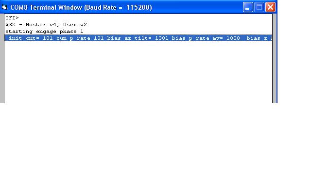
Tried setting k_xw, k_xwd and x_wheel_rate to 0 and also printing bias_az_tilt on the terminal screen. Now I have a problem that the bbot never gets to phase 2, but just stays in phase 1, not sure why. I also noticed that the reading on the screen doesn’t get refreshed as I move the bbot. I thought that the readings during steady state are taken 100 times at 18.5 usec rate for the duration of 2 sec. That is not what I see on the screen. The reading is taken once and only once. The tilt reading during balancing is about 1300 (raw value) I presume, while in the code, this is set to 35, so there is some discrepancy there. Attached is my term screen shot. Any comment on this? Thanks.
// RAY M.
P.S. I still have no luck in obtaining the white paper, as this was not included in the ZIP file with the code. Neither of the links mentioned before worked for me. I will mail you the last 2 pages of the N&V article tomorrow. Sorry for the delay. This project is getting under my skin and I really want to make my bbot to work with and without the remote and of course with the encoders.