Working Vex Pendulum Balance Robot

MarkO, on second look, these are for the realtime vex code. We want the links for the white paper which has the derivation of a dynamic model of the bbot and the simulation code targeted for the control system analysis programs MATLAB and its free version OCTAVE. Simulation code in the appendix must be copied as a text file and saved as a .m file per instructions.

The description of file is at:

https://vexforum.com/local_links.php?catid=6er.

The direct link to the white paper is :

[https://vexforum.com/local_links.php?action=jump&id=54&catid=6

Hope these work!](https://vexforum.com/local_links.php?action=jump&id=54&catid=6)

Ok, now check the freq and L_cg again. These are inconsistent still.

Be careful here… make sure you look at the proc_accel function to understand how it works. There are two biases invoved, one to give zero at o g and the other to offset az_tilt to zero at the balance position.

 az= ((int)az_raw- bias_z_acc)*sfacc ; // unit mg---this is absolute az.

az_tilt = az - bias_az_tilt*sfacc; //unit mg—this is relative az

The az_raw has a spec value of 1500mv +_300mv at zero g. My imu was on the high side at 1800mv but you must determine what your imu reads at zero g. You can get a good estimate by tilting the accel to have gravity input +1g and -1g as determined by the maximum and minimum readings. Then average these values. This is compensated for by setting param bias_z_acc =1800 for the first line. az_tilt is relative to the balance point. My bot is not symmetric, so it has a slight tilt at balance.

bias_az_tilt = az_raw (at balance) - bias_z_acc which is only 35mv for me. Once this is set, az_tilt should read zero at balance.

You just biased az out of the ball park so it never got into the engage az window which is necessary to get to phase 2.

The print during init phase only occurs at exit of init phase 0. Put your debug prints where I suggested to stay away from logic blocks.

.

This link gives me this page:https://vexforum.com/attachment.php?attachmentid=239&stc=1&d=1196351417

[quote]
The direct link to the white paper is :

[https://vexforum.com/local_links.php?action=jump&id=54&catid=6

Hope these work!](https://vexforum.com/local_links.php?action=jump&id=54&catid=6)This link gets me the White Paper… Thanks…
[/quote]

Got the white paper. Thanks Chris and MarkO.

I will put my debug printf in “bbot_user_routines.c” at the end of “void read_sensors ( void )”, as:

printf(" p_rate_raw= %d az_raw= %d lt_enc_raw= %d rt_enc_raw= %d \n", p_rate_raw,az_raw,lt_encoder_raw,rt_encoder_raw);

printf(" az_raw= %d bias_z_acc= %d az_tilt= %d bias_az_tilt= %d \n",
az_raw, bias_z_acc, az_tilt, bias_az_tilt);

I hope this will give me the readings at the rate of 20 or so /sec, so I can see things changing in real time. The code is hard to read for person like me who has been out of C programming for 20 years, but I am getting there. There are still pieces of code that I don’t undestand. It would be nice to have an algorhitm with all the relevant functions and where they get called from. I may sketch something up later.

rgds

// RAY M.

Maybe I can jump start your logic flows:
The functions in bbot_user_routines.c don’t do anything until they are called.
The calling is initiated from the main switch loop located in Process_Data_From_Master_uP(void) . The main switch loop has three phases (data flow paths) which are entered consecutively based upon meeting the criteria for entering the next phase. Each phase is responsible for calling and processing its own sensor data.

Phase 0 is the init phase. It only reads raw sensor data for initializing. When done forces phase 1.

Phase 1 is the engage phase. Calling engage() reads and processes sensor data and waits for the engage criteria to occur. When satisfied, it forces phase 2 and initializes the cum encoder and the tilt angle filter.

Phase 2 Here rc controller cmds are read and balance , rotation and motor command conditioning functions are called. balance() is given the responsibility for making the calls to proc_sensor() which makes data available to all other functions.

The program will stay in phase 2 until an overtilt() function puts it back into the engage phase 1 where it waits again to engage.

Since you will always go through one of these phases each time you enter Process_Data_From_Master_uP(void) someone will always be calling read_sensor(), but only phase 1 and 2 will call process_sensors().

At the end of the sw(phase) after the motor cmds are set, there is a counter test which allows you to limit the print calls to keep you from getting swamped by 50/s calls. This is where I put print calls unless it is absolutely necessary to mess up a function. Most variables are global so any functions setting a value is good for all.

My processing logic reads like this:

void Process_Data_From_Master_uP(void) {
cum_1=cum_1+1.; // increment print counter
//************************** main balance phase loop
switch ( phase )
{
case 0
{ //init_sensors phase code
break;}

              case 1 

{//engage phase code
break;}

             case 2 (default) 

{//balance phase + stuff code
//read rc inputs
//compute the symmetric command for balancing
//compute the rotational command
//sum symmetric and rotational commands
//add biases to compensate for controller dz
//shut off motors if over tilt condition and reset to engage phase 1
}
}

pwm03=pwm_rt ;//right motor
pwm04=pwm_lt ;// left motor

//**end main balance loop ********************

// Now check if we want print
if(cum_1>25) //print out every 25 loops…adjust this for frequency of print
{
// some typical prints I used
printf(" az= %d az_tilt= %d az_raw = %d \n" ,(int)az, (int)az_tilt, (int)az_raw ) ;

printf(“pwm_cmd_sym = %d pwm_cmd_rt = %d pwm_cmd_lt = %d \n”, pwm_cmd_sym, pwm_cmd_rt, pwm_cmd_lt);

//comment these print statements when finished debugging

cum_1=0.;} // reset print loop counter

}
} //end Process_Data_From_Master_uP()

My functions are hierarchical and easiest to understand if you start from a switch phase function and work down to the core functions that support the top level function.

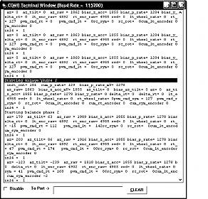
Thanks Chris. That explains lots of things. Attached is my output after printf. As you can see, the output lines are appended, one after another, which looks a bit messy. I would like to see only 2 lines with new value overwriting the old value. Do you know how to do that?

// RAY M.

P.S. Still waiting for the encoders.

… and here is the attachment.

trying the attachment second time.

Try this one: removed the \n
printf(" p_rate_raw= %d az_raw= %d lt_enc_raw= %d rt_enc_raw= %d ", p_rate_raw,az_raw,lt_encoder_raw,rt_encoder_raw);

Well, I spent a bit of time today trying to calibrate my bbot raw readings during phase 1, while balancing at rest. It turned out that both “bias_z_acc”, as well as “bias_p_rate” had to be changed from 1800 to 1855 and from 1500 to 1284 respectively. This is all based on terminal readings (see attached). After this I can notice a positive change in my bbot motor responsiveness. They still lag so the bbot still doesn’t balance, but it is getting close. I think that I now achieved my goal which was to get the bbot to the point where it is close to your bbot drive, without the encoders. Your bbot still drives a bit nicer them mine without the encoders but they are close. I think I’ll get my encoders on Monday, install them and do another test of the code on Tuesday.

Now a dumb question. Chris, am I right in assuming that you don’t determine the “bias_z_acc” and “bias_p_rate” dynamically during phase 1, but instead they are set statically in “bbot_user_routies.c”. Second comment: I would like to be able to have the code to read the battery level and adjust the motor torque accordingly. That is, as the battery depletes, motors should drive with slightly more torque, until the battery is depleted beyond certain point (say 80%). I haven’t seen that this is taken care of in the code, maybe I missed it.

// RAY M.
v1.9_term_screen.jpg

I can see there is still some confusion here. Its a little tricky. Normally, all constants would be set as #define’s in bbot_user_routine.h , but with the sensors I knew I would be dynamically changing some of them , so I just put the biases all as variables. The accelerometer biases “bias_z_acc” etc are initialized at the values shown in bbot_user_routine.c and are not dynamically changed. The bias_p_rate , however, is dynamically determined. I just initialized it at the spec bias to be close but it could be initialized at any value since it is reset dynamically by the init_rate_gyros() function.

I believe that you still are trying to use bias_z_acc to zero out az_tilt at balance point. Reread #post 42 again carefully. Your biases certainly could be different from mine since they are radiometric and they have a wide spec tolerance too. If you are setting bias_z_acc…turn your imu such that the sensitive axis is in a plane parallel to the floor. This is about as close to zero g you can get. With the bot stationary, read the raw value and that is your bias_z_acc. It has nothing to do with balance. Do this for all accs and they are probably set for good.

Now put your robot in perfect balance on its wheels and read az_raw. Then

bias_az_tilt = az_raw(balance) - bias_z_acc

“bias_az_tilt” is calculated by hand and is a constant rather than an initial condition so I placed it in bbot_user_routine.h as a define parameter. I knew this would be fooled around with as your balance point changed with configuration. Nothing dynamic.

As a check, in the non-autonomous mode, turn your controller off. This will shut your motors down but still allow the phases to operate. Once you get to engage or balance phase, az_tilt will be computed. If you print out its value and hold the bot exactly in balance it shoud read zero or at least within your ability to repeat a balance point angle.

Wouldn’t hurt. I considered it but chose not to for the bbot. The simulation shows it stable for even a 67% voltage drop. The eigen values at 100% are -6.9,-6.7 and at 67% they are -6.5, -2.5. So it is slower and if you were riding it, probably noticible. I have plans for this capability for the segway we are building.

Chris, roger your last post. I got it now. Thanks. I studied your code for the most of today. Just for the fun of it, I made several changes to bbot_user_routines.c so that the accel and gyro readings are taken in real time instead of averaging 8 samples of accel and 16 samples of gyro. This did make a HUGE difference in bbot motor responsiveness. I think that to excessive sampling could be the cause of the motor lag in my case. In fact, I now have motors that drive back and forth faster then gyro and accel data gets processed and filtered. I would like to add delay in user_routines.c, that would slow down the motor drive (just before the drive is called), giving enough time for sensor data processing and filtering. Does anyone know how to write or use a delay function? I need to be able to add delay in say 20 or 50 msec increments. Thanks.

P.S. I am also working on the encoders tonight.

// RAY M.

Ray,
What you say doesn’t make sense. The motors are updated on each 18.5 ms cycle and so is everything else, including the sensor processing. The extra a/d reads were timed and are well within 18.5ms frame. I suspect that you have added some print statements and the loop timing is exceeding the 18.5ms. You cant really run real time with print statements going. The few that I use are one shots prior to the balance phase. Comment all your print statements and if you still see the effect, then post your read_sensor() function and we’ll take a look. You don’t want to add delays.

Chris,

I am doing a lot of printing, probably too much. You could Unzip and try to run the attached HEX code w/out the encoders, and you will see what I am talking about. The motors drive too fast and bbot doesn’t balance. It seems like the motor drive and the sensors processing are out of sync. I don’t think that commenting out the print statements will make the original code motors respond faster. I also attach my modified bbot_user_routines.c and user_routines.c, that go with this HEX. The biggest problem is that I have not yet determined why motor drive gets slowed down so much, when I use your original code with sampling. I also determined that it is enough to do EITHER accl, or gyro, or both samplings to see motor drive slow down.

Different question: Could you please explain what kind of testing was this code from user_routines.c, used for. It seems that you did this before you added the encoders:

void Process_Data_From_Master_uP(void)
{unsigned long time; int value = 0; int max_delta = 650;
Getdata(&rxdata); /* Get fresh data from the master microprocessor. */

Default_Routine(); //Optional. See below.
rc_dig_out16 = 0; //turn off led//

/* Add your own code here. */
cum_1=cum_1+1.;
//cnt_1=0 ;
//time_start=Get_Time();
////while (cnt_1<100)
//{ value =Get_Analog_Value(1); cnt_1=cnt_1 + 1;}
//read_sensors();//takes 3ms to run this

//filter_sensors();

//pwm03=pwm127+pwm127; //this is for test purposes only
//pwm04=pwm127+pwm127; //this is for test purposes only
//************************** main balance phase loop *****************
bal_bot_ad_auto.zip (18.4 KB)
bbot_user_routines.c (15.9 KB)
user_routines.c (16.6 KB)

There is no probably about it!!!
Ray, you’re learning the hard way…but I’ve warned you about this many times. The overhead of the print statements is very high and you must use only one or two at most to be safe. There is nothing wrong with the read_sensor() function. You have just eaten the processing margin up with your prints and left nothing for it to use.

I’m going to ask a favor of you Ray. If you want to take advantage of my experience with this code, then don’t make structural changes until you have your encoders running. I know its tempting to start simplifying and integrating functions but I’ve spent a lot of time with this code , I understand it thourghly and I know it works. I was careful to maintain functional segragation to allow methodical debugging of each level of functionality with simple print statements. I know the code can be simplified by eliminating some of the core functions through integration but please postpone that until later when you make it your own code. For example, I gave read_sensors() the task to get only raw voltage and proc_sensors() the task to get engineering units. You have now mixed these functions, which is ok, but distorts the meaning of functional segragation.

That code measured the time for a hundred a/d reads I commented that it was on the oder of a few ms.

Ok,here is what I recommed you do.
First, eliminate all the comments you added to the sw phase. Several in the init phase are wrong anyway. Try to restore the code to its original state. The seemingly innocent printf(“********************”') add unnecessary delays.

Second, comment out all but one or two prints in the print loop necessary to focus on a particular problem. General instrumentation prints cannot be tolerated.

Third, add the loop timer to make sure that your prints are not hurting you.
Use code similar to below. Measure loop time without any prints and then add them one at a time and make sure that you do not exceed 18.5 ms.

void Process_Data_From_Master_uP(void)
{unsigned long time; int value = 0; int max_delta = 650;
Getdata(&rxdata); /* Get fresh data from the master microprocessor. */

time_start=Get_Time();// initialize your loop timers

//************************** start main balance phase loop
… balance functions
//**************************end main balance phase loop

if( cum_1 > 25. ) // print every 25 cycles
{

// add you print statements here

time=Get_Time(); // make sure this is after all your prints
printf( “loop_time= %d\n”, (time-time_start)) ; // here is your loop time

}//end print loop

Putdata(&txdata); /* DO NOT CHANGE! */
}

Sorry Chris. I didn’t want to offend you. This sounds like a good advise so I’l try this out with the encoders hopefully tonight. I agree that it is critical to measure the loop cycle, because I see a lag of about 700-800 msec between the bbot tilt and the motors drive and I cannot figure out how that time gets consumed. Thanks a lot. I really appreciate all the help you are giving me.

// RAY M.

Believe me Ray, I’m not offended, only frustrated with your insistence on adding massive debug statements when I’ve counseled you against that many times. My experience tells me that is the primary source of your problems and delays even though your still seem to doubt it. Once you exceed the 18.5ms timing in the main balance loop, the main processor interrupts the code and services the pwm outputs whether they have been updated or not. Once this happens your loop timing is destroyed and you will get garbage out. Most of your prints have no meaning once they have been interrupted and you are trying to solve a nonexistent timing problem and wasting your time and mine trying to debug them.

If you simply eliminate the excess debugs and spend your time making sure the sensor interfaces are correct…ie scaling, biases and of course sign…the code will work fine since you are using the same sensors.

Sorry Chris, but I disagree. The problem I had at the beginning was excessive lag in motor drive which was way too slow for the sensor reading. That is why I started adding debug statements, very few to start with. This problem was there from my Day 1 of working on this project. BTW, I commented out ALL print statements and I see no improvement. I haven’t measured the loop time yet. So I am giving up on this and focusing on working with the encoders and your original code, measuring how long the loop lasts, beginning to end. If the loop turns out to be taking too long, I may ask you to help me find out why, if you don’t mind. Thanks.

// RAY M

Ok , very sorry Ray , thats the first time you stated that you were observing the problem with the print statements commented . Funny, I assumed that you were using the prints to see the problem and the code you posted seemed to confirm that. Glad you clarified this so lets move on. At least we got some discussion on loop timing. :slight_smile:

Tell me if this is what you are seeing:

You tilt the robot about 5 degs and nothing happens …you continue increasing the tilt and the motors finally kick in to correct the tilt.

If this is the case then welcome to the world of vex controller dz and vex motor/axle friction torque losses. It will become your worst nightmare.

The PWM motor command to get these wheels started with the bbot load on them is 15 to 20 counts at least for mine. Refer to appendix G of the white paper for some test results.

I use a k_p gain of .433 pwm/mrad which is 7.5 pwm/deg and it takes about 2 deg of tilt just to get the wheels started. The dz compensation is designed to help with this , but after lots of tuning, I was still left with a significant limit cycle. I eventually set the dz compensation to zero to limit wear on my motor gears and I now live with a slower pause and jerk motion rather than a faster continuous jerking limit cycle.

The encoders will help somewhat with speeding up your response.

That was/is exactly the problem, you tilt the bbot 5-10 maybe 20 deg and motors do not turn. Then you tilt 45 or 60 deg and they suddenly kick in, by which time the bbot is on its nose. This is the problem I have been seeing from day 1 with the original code. Then we got talking about the torque and the weight of the bbot and we both got sidetracked on printing/debugging. I see in the original code that you have 2 constants dz_comp_lt and dz_comp_rt set to 5 not 0 and you have dz_comp( ) function in bbot_user_routines, which is called from user_routines.c → default: switch. I also see k_p and k_p_rate that you told me to increase 2 fold, at the beginning of the thread, after we started talking. This didn’t make a significant improvement to the performance. From your last reply, I think you are saying that k_p (set to 0.433), decides the tilt angle kick off for the motors, while in non-auto mode. Higher the k_p lower the tilt angle to engage the motors. I don’t see where dz_comp lt and rt are set to 0. Also, could it be that dz_comp( ) only works in non-autonomous mode and it would not work in autonomous mode? I am still 100% in the autonomous mode. That would make sense.

I got my left encoder mounted and will be mounting the right one tonight. I had to hand craft the brackets, drill the holes, shim the gear, build the cables etc., which all turned out to be more difficult then I thought. Finally I am getting very close to the first full project test run and I am very excited about it.

thanks a lot for your continuing help

// RAY M