Source Code
TankDriveCommands.zip (93.1 KB)
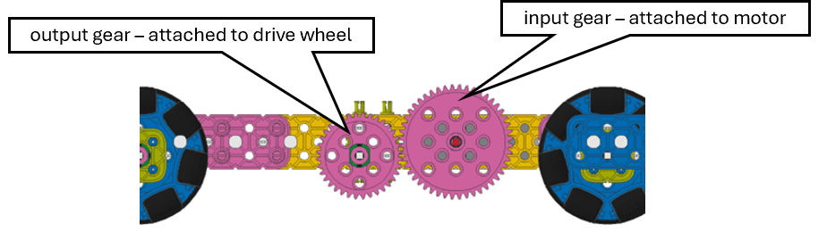
SnapCAD Drawing of Bot drivetrain used
CAD Drivetrain.zip (4.4 KB)
Theory:
Moving a bot with wheels a desired distance involves turning the wheels the correct number of turns to cover the desired distance. The equation to determine how many turns the motor must make to drive the bot the desired distance is listed below.
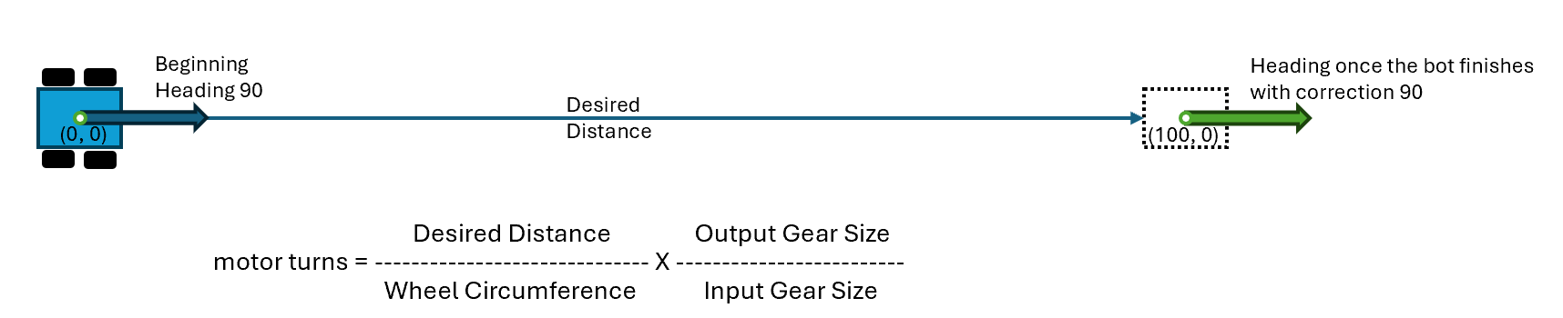
The equation above is derived from first calculating the number of wheel turns needed to cover the desired distance. Next the gear ratio of “out” over “in” is applied to calculate the number of motor turns needed.
Both the right and left motors (on a tank drivetrain) need to complete the turns at the same angular velocity simultaneously for the bot to drive the desired distance in a straight line. If the motors/wheels – for any reason - start to turn at different velocities, the bot will drift off the desired heading.
The figure below Illustrates drift.

Drift is the amount of uncorrected deviation a bot will experience on a given heading, for a defined distance, at a constant velocity. Drift is measured by two data points:
- The x and y coordinate deltas. For example, you can see from the image above that the center point of the bot without correction is positioned below on the y axis and behind on the x axis. This can be represented as a delta x and delta y values compared to the ideal as shown below. (100 – 98, 0 – 20) or Δ (2, -20).
- The change of the heading . For example, you can see that the bot without correction ended with a different heading of 97.
These errors will compound as the bot works it way thorough a set of navigation steps leading to unpredictable results.
Download the code folder zip file at the top of post. Unzip the files into a new folder and open the folder in Visual Studio code. Or if you choose to use VexCode IQ create a new C++ text project. Replace the generated code with the code in the main.cpp file.
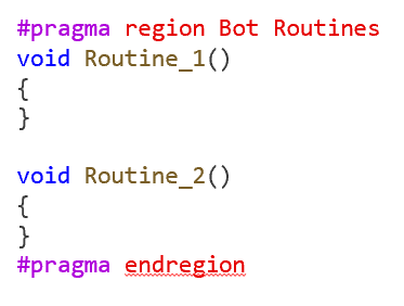
Scan through the code and you will find two routine functions which are selected and executed by the touch LEDs. The algorithm used to do this has been covered in one of my earlier posts (Using 2 TouchLEDs to select an autonomous routine, start the routine, and stop the routine mid-way. - VEX IQ General Discussion - VEX Forum). Throughout this exercise you will be developing routine code to be placed in one or other of these two functions.
Before you can run this code on your bot you will need to adjust the following parameters to fit your bot.
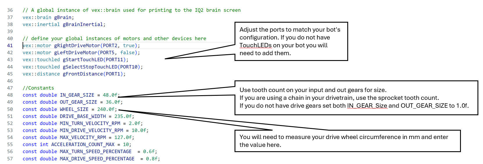
A few tips on Visual Studio Code
Visual Studio Code works with extinctions. The C++ extinctions I have installed are depicted below. The C++ IntelliSence extinction is being leveraged here via the @brief and @param attributes to allow the function information to be displayed in the IDE as shown below.
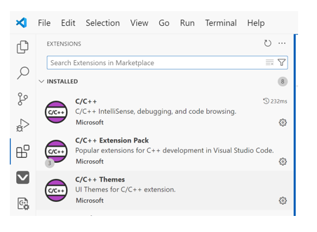
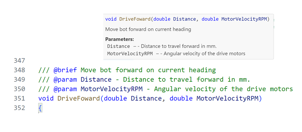
This tool will make you far more productive when coding.
Interspersed throughout the code are “printf” commands used for debugging which is a throwback to a programing technique used 30+ years ago. This crud form of telemetry will give you - the developer - insight into how the code logic is executing.
The method used to correct the heading of a bot is governed by the drivetrain type. In this post I will focus on the most common QI bot drivetrain. However, most of the techniques presented here can be applied to any drivetrain configuration.
A two-motor tank drivetrain consist of one motor driving one or more wheels on the right side of the bot and a second motor driving the left side. The direction and speed of the wheels determine the movements of the bot. For example, if both the right and left side wheels are moving clockwise at the same angular velocity (RPM) the bot will - in theory – move forward. If the right-side wheels roll clockwise and the left side wheels roll counterclockwise, the bot will spin around the bot’s turn radius counterclockwise.
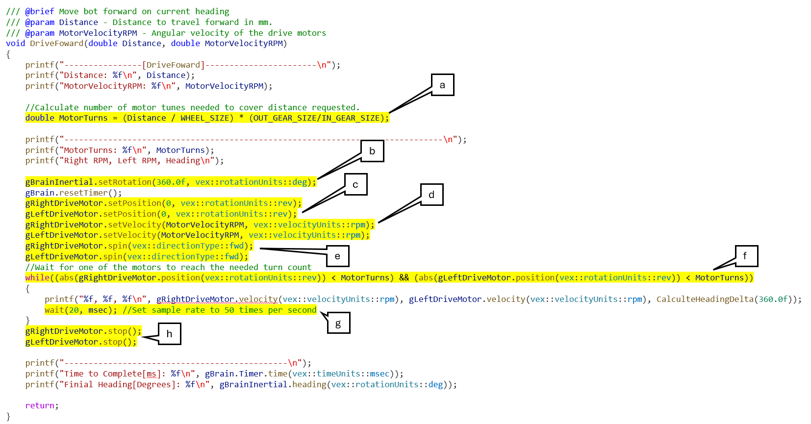
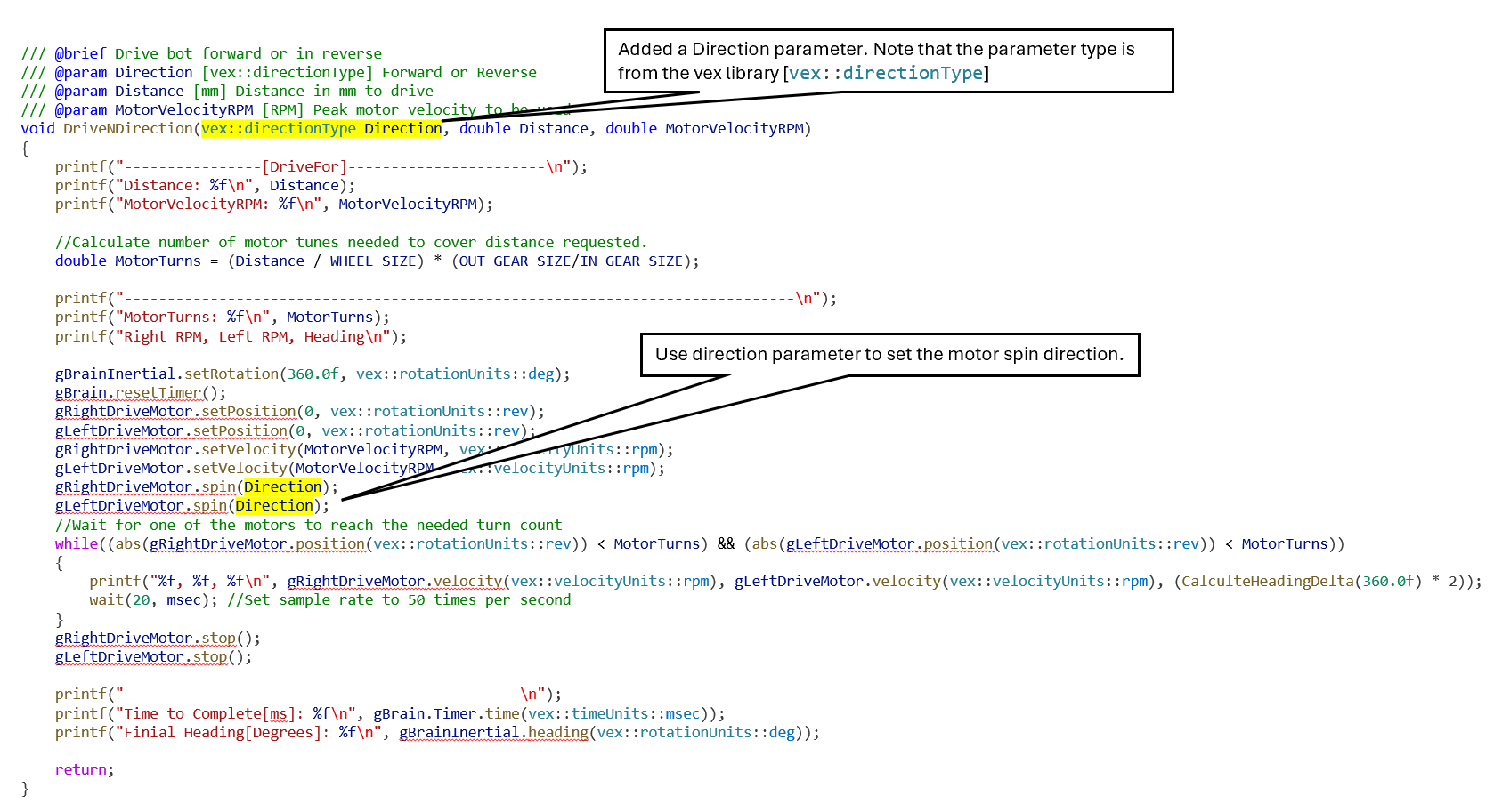
Thus, code to move a bot forward a desired distance is listed below.
Code Explanation
The function is broken down into several task (listed below) which as a whole make-up the essential programing components needed to control a bot’s movements.
Task List
a. Calculate number of motor tunes needed to cover distance requested. This is done using the equation listed below.

b. Set the internal (IQ2 brain) inertial sensor rotation to a 360-degree turn. This is done to simplify the math when calculating the heading changes. (we will cover this function later)
c. Set the right and left motor encoder positions to zero. This is done to set a zero-starting point for tracking the distance traveled.
d. Set the right and left motor velocities to the MotorVelocityRPM parameter value.
e. Spin both motors forward. The motors have been initially configured (see code snippet below) to ensure that a forward angular motion of the motors will translate to a forward motion in tank drivetrain.
![]()
f. Use a while loop to monitor both the right and left motor’s turns and exit the while loop when one of the motors has achieved the desired turns.
g. Set the sample rate for the evaluation of the while loop condition to 50 times per second.
h. Once the loop is exited stop the motors.
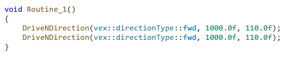
Once you have adjusted the code to fit your bot place a single DriveFoward call in the Routine_1 function and run the code by following the steps out lined below:
- Place a fully charged battery in your bot.
- Place the bot on the field in the direction you wish the bot to move.
- Run the application from the Vex IQ Gen 2 Brain or IDE interface.
- At first both the touchLEDs will be red. Wait until the “select” touchLED turns white and the other turns off.
- Press the “select” touchLED once slowly or until you see that it is blue in color and that the other touchLED (“Start”) is green.
- Press the green touchLED to execute routine #2.
Note how far the bot goes and how much it drifts. Note in the terminal (Visual Studio Code) or console (VexCode IQ) the time to complete and the final bot heading.
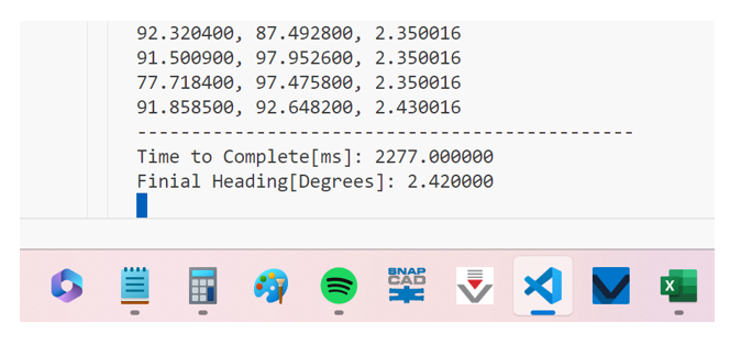
Next capture the performance telemetry (see below) and use a tool like Excel to graph the data points as shown below. You will need to copy the data from the terminal and past it into NotePad. Save the file using the extension “.csv” if you want to use Excel.
The graph you get will show you the right and left motor’s recorded RPMs. If you filter the noise, you will get a constant curve showing how the motors came up to speed and what the average peek speed is. You will want to take note if the bot motors reached the desired speed. If not, note how far below the desired speed the bot fell.

Next you will want to do a spin test on your bot. To do this prop the bot up so that the wheels can spin freely (the bot should not move) and rerun the code. The graph below shows the spin test on the same drivetrain as before. Note the changes.

Here the drive motors under load are not reaching the desired velocity and are considerably noisier. The time to peek average speed is also significantly less. Both of these findings are expected results. However, the range between minimum and maximum motor speed should have been less during the spin test or have fewer troughs. The troughs seen in the spin test above is an indication of something mechanical within the drivetrain causing power loss. In this case it is due to the use of a chain which is too tight.
I choose to include the topic of spin test in this post to point out that bot drift is often due to mechanical issues which can be mitigated. Sometimes the mechanical issue causing drift is not evident on visual inspection and reviewing motor performance curves can help trouble shoot the issue.
Now that we have a function to move a bot forward, we need to add the ability to go in both directions. The code below is based on the pervious function code with a few simple changes.
Modify the routine_1 function to call the DriveNDirection function twice as shown below.
Rerun the drive test and review the results.
Reviewing the motor performance curves shows a phase shift between the right and left motors occurring at the start and during the transition from forward to reverse. The phase shift is associated with a significant increase in heading delta also called drift (change in heading).

This finding indicates that we should look for a way to ease the motor speed transitions. The best way to accomplish this is the apply some acceleration and deceleration logic into the function.
There are numerus methods which could be used to apply acceleration / deceleration logic to ease the motor speed transitions. I have chosen to create a C++ class. A class is an encapsulation of data and function into a single type. Using this method simplifies the drive function code by abstracting away the accelerate/decelerate logic. The class I created is listed below.


Code Explanation
The logic within the “GetNextStepRPM” method is as follows:
a. Create local double NextStepRPM to hold calculated RPM value.
b. Increment member integer _step to record the number of times the method has been called.
c. If the _step value is within the steady range wait step pause and return the max. rpm value. This avoids the computation time used to calculate an RPM value.
d. If the _step value is within the decelerate range calculate the new slower PRM value.
e. If (else-block) the _step value is withing the acceleration range calculate the new faster RPM value.
f. If the _step is not the first step (>1) the wait the step pause.
g. If the _step value is greater then 1 and the function has not already returned (see “c”), pause the execution of this thread for the _stepPause amount using a wait call.
h. Check that the calculated RPM value is not less than the minimum motor RPM value. If it is less, set new RPM value to minimum motor RPM value.
i. Return new RPM value.
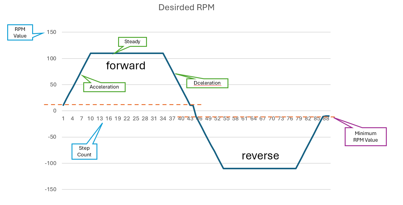
The graph below details the expected behavior of the Accelerator classes “GetNextStepRPM” method.
Here the following constructor parameter values were used:
AccStepCount: 10
SteadyStepCount: 24
DecelerationStepCount: 10
MaxMotorRPM: 110.00
I added the new class to the main.cpp file near the top between the global variables and the function definitions as shown.

Note, that in general when you add a class to a project you do it in two separate files. The first is a header file “.h” or “.hpp” which contains the class definition and a second “.cpp” file which contains the method code. However, to keep this code simple and in scope of this post I have chosen to simply add it to the main.cpp file a single code segment.
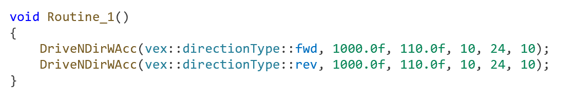
To add the accelerate/decelerate I wrote another new drive function to leverage the Accelerator class type.

Now you will need to modify the routine_1 function to call the DriveNDirWAcc function twice as shown below.
Rerun the drive test and review the results.
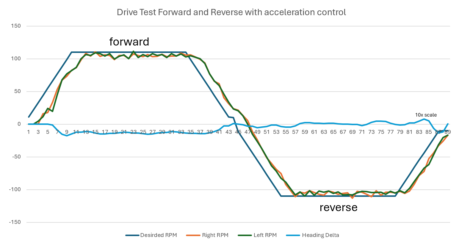
The chart below show us how easing the motor RPM transition helped to tamp down on the heading changes in both volume and frequency. The starting heading and ending heading are practically the same. Note that the pervious chart showed the heading delta in 2x scale and below the heading delta scale is 10x. This was done to help visualize the heading delts in the chart.
The performance measured here shows that the two-motor tank drivetrain design used here is reliably when run on a level and obstacle free surface. Now we need to see what would happen if the bot hits an obstacle.
The chart below indicates that the right motor hit an obstacle at sample count 20 moving forward and again at sample 60 moving in reverse. The performance curve indicates that this was a one-time event given that the motor noise level adjusted back to expected levels shortly after the event. Note that the pervious chart showed the heading delta in 10x scale and below the heading delta scale is 2x.
It would be nice to be able to able correct this heading after hitting an object. The Gen 2 QI brain has a built-in inertial sensor which can be used to detect changes in the heading.

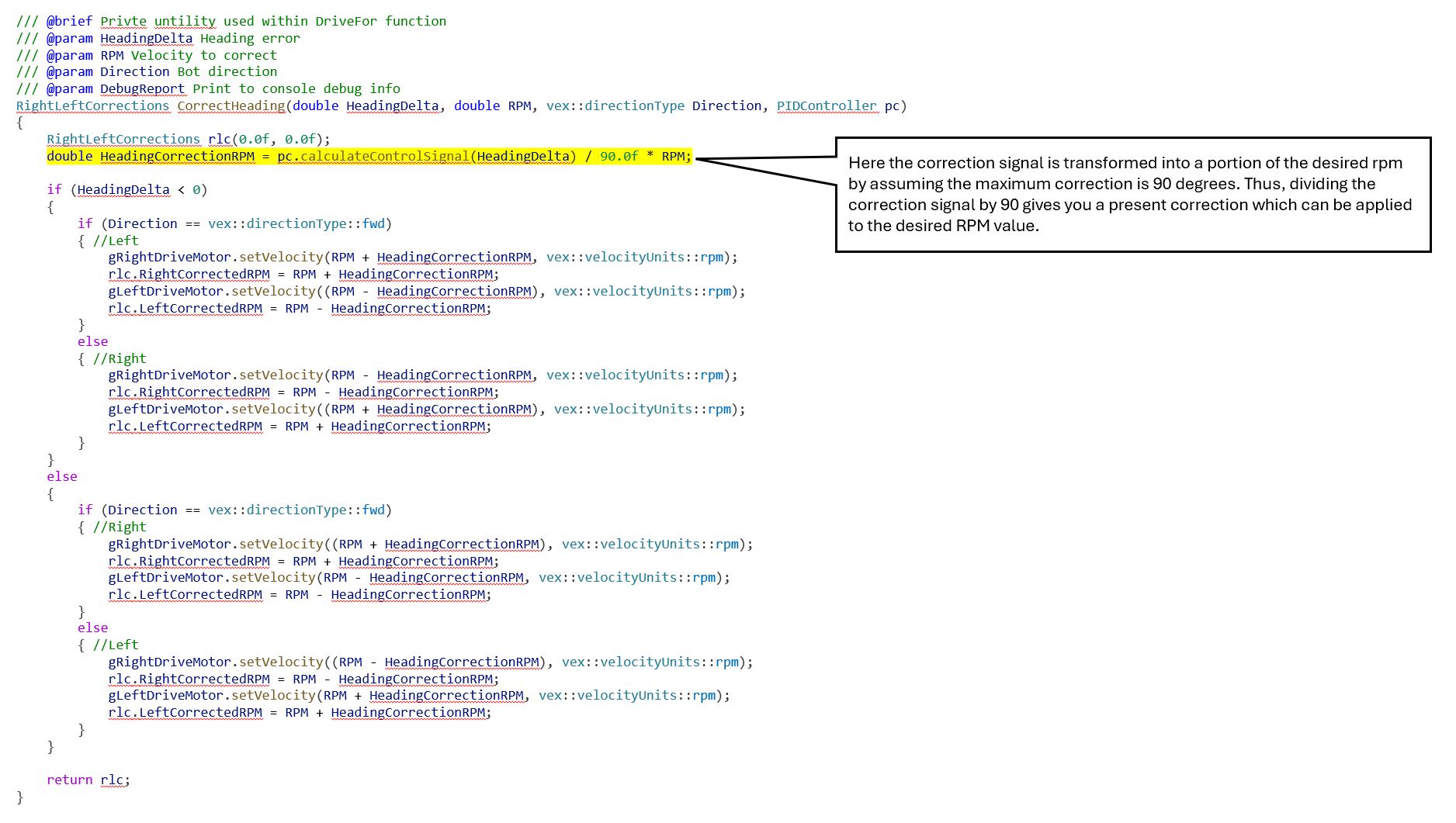
Using the heading delta as an error value a PID process control can be added to our code to correct the heading.
We need to start with the theory.

To any beginning level student this diagram looks quite complicated. However, if you focus on the components, it really is quite simple. You start with a “set point” that would be the desired value. In our project it would be the heading delta with a value of 0 (no drift). Next compare the desired value “set point” with the measured value “process variable”. The difference is the error.
The error is then used to calculate a correction. The correction is made up of 3 components:
- Proportional – simple error percentage
- Integral – sum of all errors measured during the process run
- Derivative – how much did the error increase or decrease from one sample to the next
These 3 components are each assigned a weight by a coefficient known as Kp, Ki, and Kd. The sum of the 3 components is called the control signal or just the “controller output”. The true challenge in making a PID work on your bot is to figure out the coefficients to use. But first we need to write some code to calculate the correction using the PID method.
Once again, I choose to use a class to encapsulate this functionality. The code below is the code I created to do this. There are several examples of this same code online. Please note that this code has not been optimally written. It has been written to illustrate the theory.

I added PID class to the code using the same method as I used for the Accelerator class. Next, I added a few functions. I started by creating a function to drive forward or reverse with acceleration and correction. The function code listed below is such a function.
Here I have implemented a few other coding techniques which are indicated below.
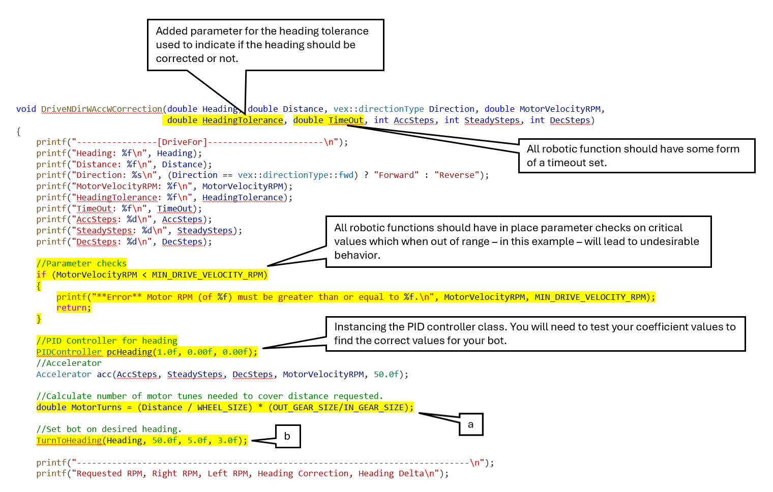
Code Explanation
As was done in the earlier versions of this function we start by (see 2-degree in code listing). This is followed by a call to turn the bot to the heading valued passed into the function (b). Next the following initialization step are completed:
a. Calculate the needed motor turns.
b. Make a call to turn the bot to the heading valued passed into the function.
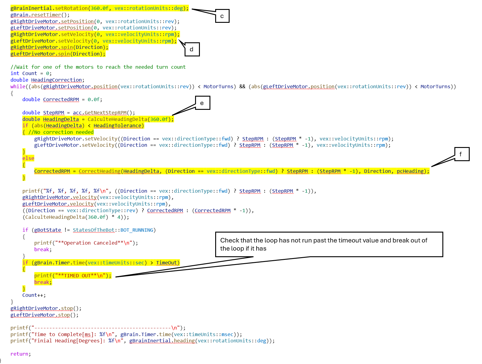
c. The internal brain inertial sensor “turn degree” is set to 360 degrees. This allows us to track the changes in bot heading without to hassle of “360 is zero” which simplifies the math. To better understand this simple trick think of a bot drifting to the right leading to heading change of +2 degrees. The inertial sensor – in our example – would read 362 degrees. Subtracting 360 from 362 would leave you with a +2-degree heading change. Now let the bot drift to the left -2 degrees. If the internal brain inertial sensor “turn degree” had been set to 0 degrees, the subtraction equation would result in a -362 degrees. However, if the internal brain inertial sensor “turn degree” had been set to 360, then the sensor would read 358 and the subtraction equation would result in -2 degrees. The value which represents the heading change correctly.
d. Set the motor velocities to zero and instruct both the right and left motors to spin in the direction indicated by the Direction parameter.
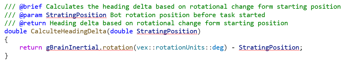
e. Calculate the heading delta using the function listed below.
f. If the heading delta is greater then the heading tolerance parameter, set motor velocities with the CorrectHeading function listed below. Otherwise, set the motor velocities with acceleration values like in the earlier DriveNDirWAcc function. The Correct heading function is intuitively coded. Basically, the left and right motor velocities are adjusted to slow down one side and speed up the other to in order to counter the drift.
To find PID coefficients (Kp, Ki, and Kd), one can use a few different methods:
- The Ziegler-system and tuning, which involves experimentally finding the ultimate gain and period of the system and then using set formulas to calculate the PID values
- Trial and error where you manually adjust the coefficients based on the system response.
- Using auto-tuning algorithms that automatically adjust the PID values based on system behavior in real-time.
I find that trial and error often sufficient when dealing with Vex IQ bots. Here are a few tips to help you get started.
- Start by setting Ki and Kd to zero.
- Set KP to 1 and increase until the response curve looks something like what is shown below.
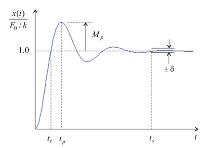
- Now start increasing the Ki until the first peak is below the desired value (or Mp is zero).
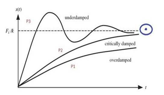
- Lastly start increasing the Kd until the curve look like what is shown below as critically damped.
Below are the results I got after setting the PID coefficients as follows:
Kp = 1.0
Ki = 0.01
Kd = 0.5

It is my hope that this post will help VexIQ teams make use process controls in their autonomous skills programs.