Expected time delta between Timer.system() and. Rotation.timestamp()

Hi, I was trying to capture data from our tracking wheels setup and not sure why I’m seeing what’s going on with the timing values comparing Timer.system() rand Rotation.timerstamp().

Based on my understanding, Rotation sensors update by default every 20ms, so a ~10ms loop capturing data should see up to 20ms delta between the system time and the sensor timestamp + some delta accounting for internal Brain and VexOS sensor update delay, so maybe up to 30ms?

What I’m seeing on the other hand is the time delta starting off being delayed between 30-40ms and slowly increasing. After about 7 seconds the delta is bouncing between 80-90ms. The code here is very simple:

def sampling_thread_callback(self):
    brain.screen.print("Sampling Thread Started")
    global run_sampling

    rot_l = [] # list for left rotation sensor
    rot_r = [] # list for right rotation sensor
    rot_s = [] # list for sideways rotation sensor

    system_times = [] # list for system times

    system_timer = Timer()

    total_samples = 0

    # Capture data
    while self.run_sampling:
        current_time = system_timer.system()
        system_times.append(current_time)

        rot_l.append([RotationLeft.position(TURNS), RotationLeft.timestamp()])
        rot_r.append([RotationRight.position(TURNS), RotationRight.timestamp()])
        rot_s.append([RotationRear.position(TURNS), RotationRear.timestamp()])

        total_samples = total_samples + 1

        wait(10, MSEC)

    # Print data 
    print("Total Samples = ", total_samples)
    print("idx, time, rotl TURNS, rotl TIME, rotr TURNS, rotr TIME, rots TURNS, rots TIME")
    wait(10,MSEC)
    for i in range(total_samples):
        rotl_val, rotl_time = rot_l[i]
        rotr_val, rotr_time = rot_r[i]
        rots_val, rots_time = rot_s[i]
        print(i, ",", system_times[i], ",", rotl_val, ",", rotl_time, ",", rotr_val, ",", rotr_time, ",", rots_val, ",", rots_time)
        wait(500,MSEC)

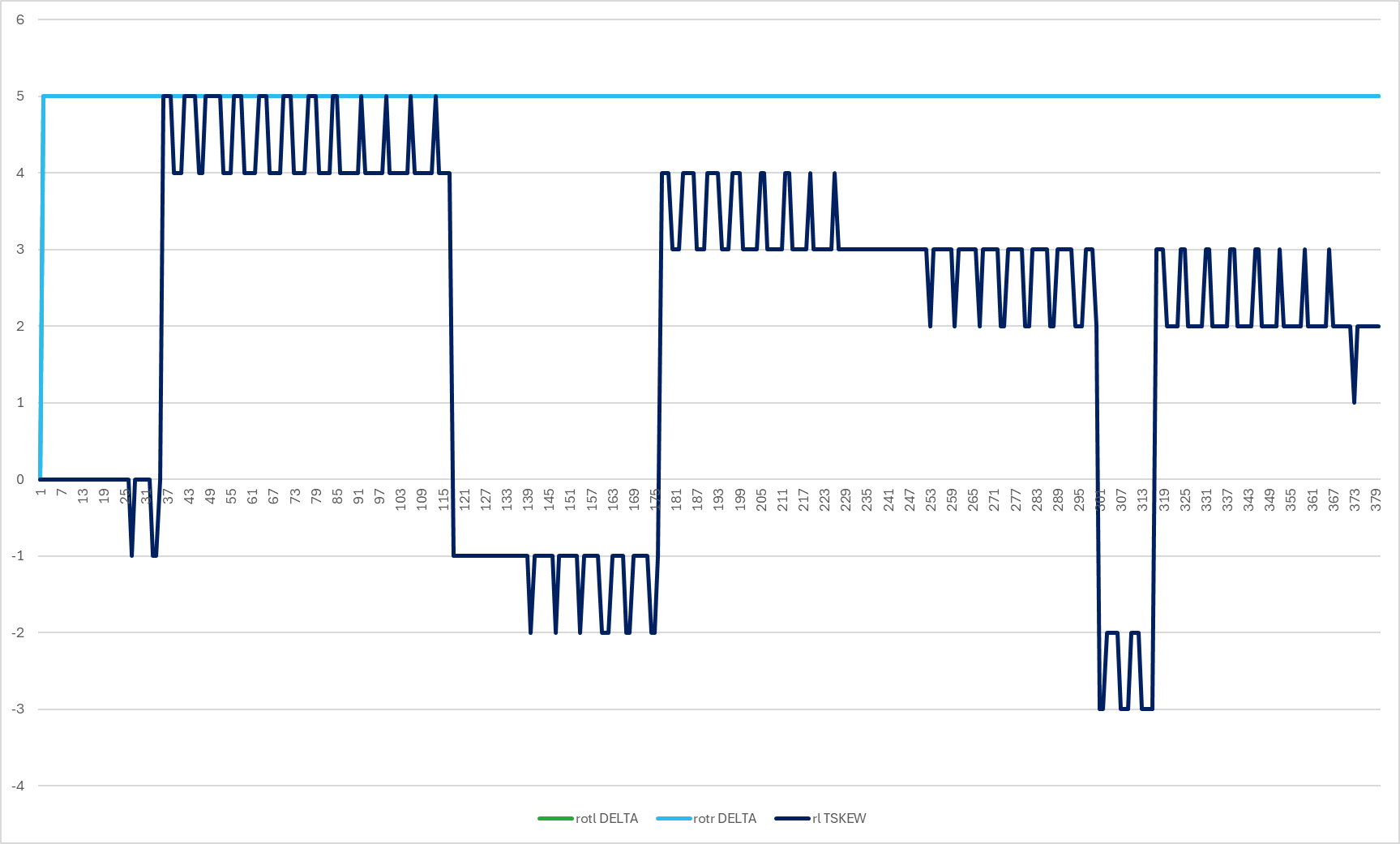
Captured results from this is below (note sideways sensor omitted for brevity). The last two columns are just the difference between the system time “Time” and the respective sensor timestamps “rotl TIME” and “rotr TIME”.

Any help appreciated here …

Thanks,
Nick

You’re witnessing clock drift (and several other factors) I believe.

Rotation.timestamp() is not the Brain’s timestamp when it recieved the packet, but rather the device’s recorded timestamp when it sent the packet. Since the clock hardware between the devnce and the brain are different (Cortex-A9 vs. Cortex-M0+) there’s always some amount hardware clock drift, though I don’t think that’s the main issue here.

There’s also the fact that you’re comparing the timestamp of when the device sent the packet vs. the time you accessed the data. Those times can be vastly different, since it takes time for the device data to be sent to the Brain and processed in the background by VEXos. VEXos will only process incoming packets from devices every 10ms by a background task, regardless of how fast the device is sending data to the brain. As such, the Device.timestamp() value will always have at minimum a ~10mS gap between packets.

There’s also the question of scheduler timings. Your code that reads the timestamp value off the sensor is not perfectly synchronized with the background task responsible for updating device data, meaning you aren’t immediately reading the data as it becomes available to you. VEX’s cooperative scheduler is doing other things between those wait(500,MSEC) calls and you don’t have exact control over when your code runs. That means there may be any amount of time between when VEXos decides to update device data in its 10mS interval and when your code actually gets to read that data.

Actually it is the time that the brain received (or rather initially processed in cpu0) the packet. Now it may take time to pass to cpu1 and then to user code. At some point, if I ever get any free time, I’ll try and reproduce what OP is seeing here.

Interesting, never knew that, though it explains a lot. A few months ago I was testing a method of more robust disconnect detection using those values and was confused why the value didn’t reset when the device lost voltage. :sweat_smile:

Is that timestamp different from the raw position getter on motors? I know that people have attempted more accurate velocity estimation using that outvalue in the past. Guess it’d still be accurate than CPU1’s clock value, but it would mean that those estimations are more off than expected.

Thanks @Tropical, yes I’m expecting some amount of internal delay for this to actually get passed through to the code itself, which is why I was expecting the delta to be more like 30ms with a fair amount of jitter. The fact that I’m seeing 30-40ms therefore at the start of sampling was a little higher than expected, but not by itself much of a concern.

However, the delta steadily increases which is not expected. Every second it seems to add about 10ms to the delta. Speaking of which, the pre-auton code takes about 3 seconds for sensor initialization, so temporarily removing this and allowing the sampling code here to start straightaway provides initial deltas more in the 10-20ms range (but then starts increasing at the same rate as before).

Nick

Thanks @jpearman. For now I’ll use the Rotation.changed() and then use the Timer.system() to act as a timestamp, although this is probably slightly delayed from what the actual timestamp would be. Doing it this way I’m seeing an average of 10ms :+1:

Related to the changed() callbacks, I had noticed previously that for the older 3-wire ports there was a filter on when changed gets called ( What is criteria to calling analog_in.changed()? - VEX V5 Technical Support - VEX Forum. Wondering if that applies to other sensors like Rotation sensor? I’ll see at least try to see if I can get it to register a 1 LSB rotation.

Nick

Just a suggestion for Vex (which has been made before), but maybe adding more details about each device’s specifications (including notes about data rates between the device and the brain/software environment) would be nice. For example, one would need to find VexForum posts (mainly from you, which sort of helps) to find information like the FOV on the Distance Sensor, it’s data update rate, etc.

Adding this data to each sensor’s Product Sheet would be nice

So one question here - can I use the relative timestamps between individual sensors (in this case rotation) as a reasonable estimate for when the sensors actually got updated relative to one another?

What I’m finding is that the changed callbacks all get called at the same system time for the three sensors, saying they’re being queued up, even though the timestamps for each sensor vary quite a bit relative to each other.

If I make the assumption that at least within the 10ms loop time things are not drifting too much, then the relative skew of the timestamps show how much the sensor readings need deskewing relative to one another. Also the callback system time then would place a lower bound of how long ago the sensor readings were updated.

If that makes sense.

Graphically here I’m showing the time delta between the current system time at the start of the sampling loop and the time that the changed callbacks get called. These are basically constant at 5ms. These are the “rotr DELTA” and rotl DELTA" lines (showing up as one light blue line). The difference in timestamps between right and left rotation sensors (“rl TSKEW”) in dark blue however bounces around quite a bit (-3ms to +5ms here).

Note this was taken from c++ with 5ms overide for datarate. Sampling loop still at 10ms.

@Tropical and others are much more familiar with this than I am, but something you’ve probably not yet encountered are the timestamps on the devices (especially the motors) resetting during the test, which indicates what they call a “microdisconnect”. See: ✨ Microdisconnect Detection · Issue #5 · LemLib/hardware · GitHub

You also may be encountering some of what Sylvie found several years ago when she was working on a velocity controller. Sylib: Smart Motor Velocity Estimation may be of interest

In reality, the motors don’t update every 5ms. They update almost every 5ms. About 1 in every 20 times, the time gap between frames is 4ms, and rarer still it takes 6ms.

Yep, the microdisconnect detection feature you linked is actually something I proposed to Liam a few months back (and what I was referring to in my reply). Typically it takes VEXos a sizeable amount of time (I think 25-50mS iirc) to actually recognize that a smart device has disconnected from the brain (believe some kind of ACK/heartbeat packet system is used). On IMUs in particular this can be disastrous if VEXos doesn’t recognize that the IMU lost voltage because the IMU will auto-calibrate upon booting again, which is the typical culprit behind people’s robots “spinning out” in autonomous.

The reason why I’m interested in whether or not motor_get_raw_position’s timestamp comes from CPU0 or the device itself is because it would make this form of disconnect detection possible (for motors at least…), and make Sylvie’s clock drift problem a bit more puzzling if the timestamp originates from the other core rather than the motors.

can I use the relative timestamps between individual sensors (in this case rotation) as a reasonable estimate for when the sensors actually got updated relative to one another?

This depends on your definition of “got updated”, I guess. The usefulness of device timestamps is dependent on how CPU0 processes incoming device data. If it’s polling based (e.g. it reads from some mailbox in an event loop with a fixed duration), then that timestamp probably gives you no value of measuring relative timing between when the two sensors actually sent new data to the brain. If it’s interrupt-based (e.g. CPU0 processes a device packet as soon as its sent over the wire) then that timestamp is probably more helpful. This is assuming you want to measure when the sensors actually recorded their data, rather than when the brain decided to process that data.

What I’m finding is that the changed callbacks all get called at the same system time for the three sensors, saying they’re being queued up, even though the timestamps for each sensor vary quite a bit relative to each other.

I’m not super familiar with how VEXcode’s event system works on the scheduler-level, but I’m going to assume that they are called sequentually as soon as the CPU1 background processing task processes new device data. In user code, this “processing” is done all at once for every port on a roughly 10mS interval from my testing, so I’d expect these events to run roughly at that same interval even for different devices. Take what I say here specifically with a rather large grain of salt though, since these are just assumptions. I know very little about VEX’s scheduler internals, particularly with regards to events.

Note this was taken from c++ with 5ms overide for datarate. Sampling loop still at 10ms.

“Data Rate” setters on sensors from my experience does not change how fast data is made available to you (the user). VEXos will still only process device information every 10 milliseconds as part of background processing. What’s being set here is probably how fast either the sensor sends data or how fast the other core (CPU0) processes that data.

tl;dr: Data recieved from devices is seemingly only made available to user code every 10mS, regardless of how fast the device is sending that information to the Brain. Device writes are immediately transmitted on the other hand. That’s why motors are 5mS write, 10mS read.

Separately, and maybe this would be for @BennyBoy , it looks like the latest version of the Vex-supplied C++ API provides this timestamp feature for all devices while in PROS it is limited to Motors. Any plans to add this for other devices, especially in light of the microdisconnects w/ IMUs?

The timestamp value for non-motors that’s seen in the VEXcode APIs would be useless for micro-disconnect detection since they are a timestamp recorded by the brain rather than the device as James mentioned. When a device disconnects, the brain will stop processing new packets from the device and that timestamp will simply freeze showing the last processed packet time. Once VEXos catches on that the device is no longer responding to communication, the timestamp will change to zero (but this requires that 25-50mS detection period). After reconnecting, the timestamp will resume counting.

The one returned by the raw motor getter is supposedly different which allows for this (although I haven’t confirmed this).

I’ll send this to the team but I have no clue when this functionality was added or how we can access it, I’ll look around.

June 2020, released in V1.0.12

Thanks @Tropical and @Mentor_355U!

Yeah, so the datarate did turn out to be 10ms after all that. I guess I should have reread the post again: Rotation sensor update rate? (Optical shaft encoder vs rotation sensor?) - Programming Support - VEX Forum. But at least better than the 20ms which is where I started.

Disconnects are interesting - will need to pay attention to that.

The changed callbacks didn’t quite work out after all that. Turns out that by the time the main odometry loop starts the saved sensor readings were quite often stale. Not sure if this was because of filtering of values in the API or scheduling.

So the best I seem to be able to do here is to still run the sensor sampling loop every 5ms to try to get the updated value as close as reasonable without taking up too much CPU time. These values then get placed in a small buffer that keeps track of the last few readings along with their timestamps. The timestamps are the best proxy I can find for that actual time of the sensor reading.

The main odometry loop then runs at 10ms and uses a filter (linear interpolation for now) to retime/resample the readings. Results for a robot driving straight for 1m below. This is only the heading part of the calculation.

First Chart: This is where I started with 20ms datarate and no interpolation. You can see the discontinuities where the sensors switch relative places in time with one another. The gyro is included here as a reference. All values in degrees.

Second Chart: 10ms samples with linear interpolation for retiming. Still a bit noisy, but much improved. Sorry no gyro here.

Anyway, onto figuring out which filter to use …