Motor torque-speed curves - REV2

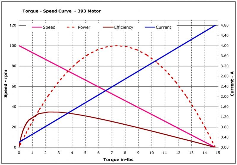
Back in May I had posted the theoretical speed-torque curves for the 393 and 269 motors. Other forum members did experiments and IFI confirmed that the curves matched their test data, Life was good.

In another thread I had used the theoretical data along with other measurement to estimate motor current based on commanded and measured speeds. IFI posted that they were also doing tests and would release data that would help us all. The data was released in June and for the 269 motor pretty much matched the theoretical results. The data for the 393, however, was quite different and this, along with a couple of the conclusions drawn from the data, has been bugging me since then. At the end of June IFI changed the posted spec for the 393 motor on both the product page and wiki, the new spec has the maximum stall current 33% higher than previously shown along with a modest increase in torque and higher no load current.

So what is an engineer to do? Well the only thing I know how which is to buy myself some motors and do my own tests.

Issue 1, max stall current has increased from 3.6A to 4.8A

This is pretty easy to test despite suggestions to the contrary.

First off, measure the resistance of the motor windings, I measured two motors and found both are nominally 1.5 ohms. So for 7.2V across the motor when it is stalled and back emf not involved, ohms law gives us a current of 7.2/1.5 = 4.8A, what a surprise.

Secondly, setup the scope to measure current and hit the motor with a 7.2V impulse then look at the resulting current waveform. As the motor is initially stationary there will be no back emf and the current for the first few mS will esentially be the stall current. The motor does present an inductance as well as resistance so the current will also build up to the maximum value, however, the time constant for this is smaller than the time it takes for the motor to start moving. I measure a 393 hooked to a MC29 connected to port 9 on my cortex. Power comes from a bench supply i drag home from work able to supply regulated 7.2V at up to 20A. Here is the scope waveform.

393_fullspeed_noload_1_M2.jpg

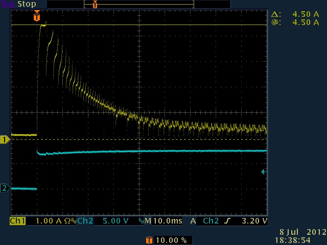
The yellow trace shows current, the blue one the input voltage drive. I measure 4.5A in the first 2 or 3mS before the current starts to drop as the motor turns. This is not quite the theoretical 4.8A but close enough bearing in mind that as well as the motor windings there are two PTS devices and a couple of less than perfect connections in the circuit all adding some resistance.

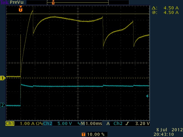
Here is the same thing with an expanded timebase (captured at a later time so test conditions changed slightly).

The current tales about 1mS to build to the maximum value, close to the 4.8A theoretical number.

393_fullspeed_noload_3_M2.jpg

One final test, stall the motor at maximum power, measure the current.

393_stalled_power128.jpg

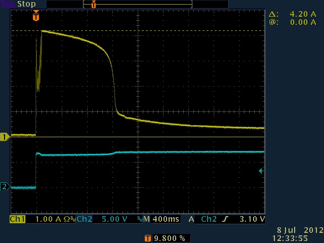
This was actually a different motor so slightly different result, approximately the same current, PTC trips in 1.2 seconds which is when the current drops from the 4.2A maximum to about 1A and then slowly to 400mA. Slightly strange behavior here but that’s to be looked at on another day.

So the first conclusion based on these measurements is that indeed the old 3.6A spec was a little optimistic and 4.8A a more realistic number.

Issue 2, Paul states that, based on his interns measurements, the maximum recommended input voltage is 4V, corresponding to a motor drive command value of about 64, for a stalled motor not to trip the PTC quickly. The data shows that at this voltage 2.82A will be flowing through the motor.

In this condition the PTC will not trip for 3 minutes.

I say, no way!

The PTC in the 393 has a trip current of 1.8A (and a maximum time to trip of 5.9 seconds at 9A) but I’ve found that the datasheet for PTC devices always seems to be optimistic.

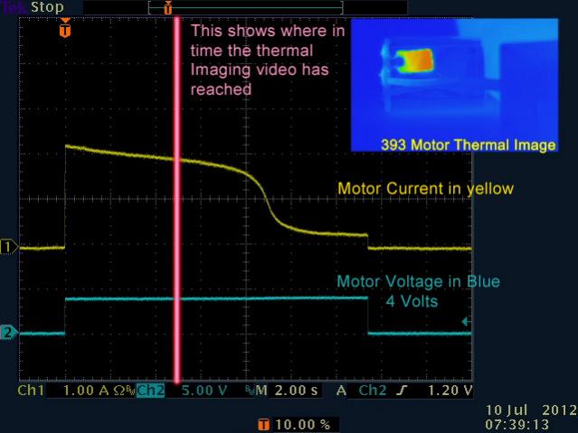
So I send a command to the motor with a value of 64, stall it, and capture the current on the scope showing when the PTC trips.

393_stalled_power64.jpg

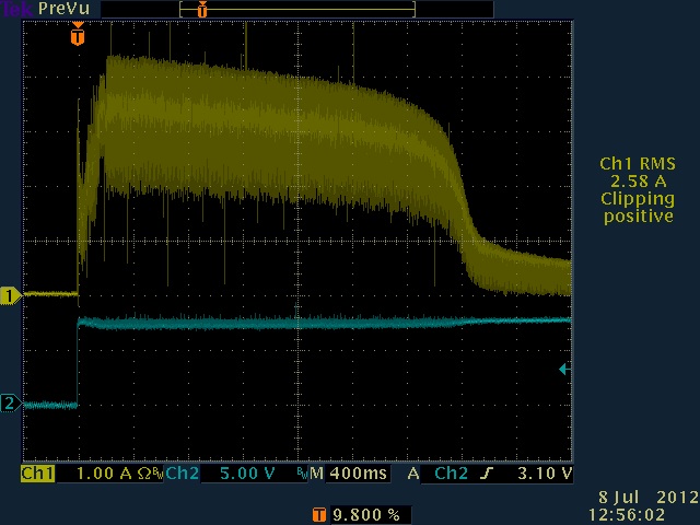
Again the yellow trace shows current, it swings between 4.5A and 2A as the PWM voltage turns on and off. The scope measures 2.58A RMS current but it is being tricked as the current falls, its probably nearer to 3A. The PTC trips in a little under 3 seconds, so maybe the “+3” in the IFI results means 3 seconds rather than 3 minutes, I can believe that.

Conclusion, with a command value of 64, a stalled 393 motor will trip the PTC in around 3 seconds.

Issue 3, the no load current is now specified as 370mA.

It used to be 150mA, so has it really changed?

Under a no load condition the current waveform is quite complex and looks like this.

393_fullspeed_noload.jpg

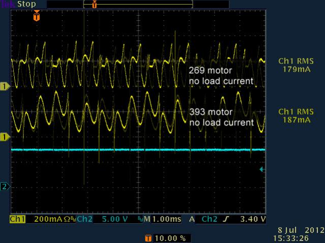
I show the no load current for both the 269 and 393 motors in this trace, they have different characteristics but on the whole are similar in amplitude and peak at less than 400mA. The scope measures RMS current for the 393 as 187mA (and 205mA in the reverse direction not shown here) so I’m going to say a more reasonable value is 200mA. I only tested two motors for this so perhaps there are some outside this range, anyway, for the revised graphs I’m going with the 200mA value.

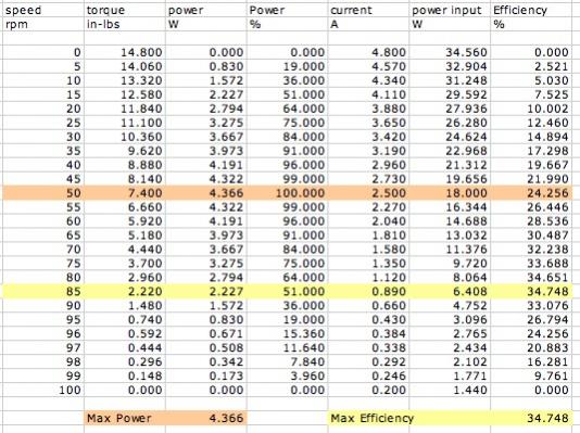
**Issue 4, torque is increased from 13.5 in-lbs to 14.76 in-lbs.
**

I still don’t have a way of measuring this that I’m comfortable with so I’m passing on this one and just taking IFIs word for it.

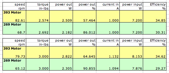
I will post the revised torque-speed graphs in the next post and than revisit some of the old comparisons with the 269 motor in a subsequent one.

.

4 Likes

And here are my revised theoretical graphs based in the new IFI specs with the adjusted no load current. I’m leaving the no load rpm as 100 rpm even though we measure slightly higher than that.

torque_speed_393_table.jpg

And for reference, the data for the 269 motor. This is also slightly revised and uses 2.8A as the stall current rather than the previous 2.6A. This was also part of the IFI posted data and confirmed by measurement.

torque_speed_269_table.jpg

3 Likes

Lets take a look at how some of the previous calculations work with the new numbers.

This post was comparing the 2011 (Gateway) rules with the 2012 (Sack Attack) rules concerning the umber of 393 motors allowed.

An updated version of this using the new stall currents.

Worst case condition, all motors stalled
Gateway
4 x 4.8A + 6 x 2.8A = 36A

Sack Attack
10 x 4.8A = 48A

It doesn’t really change the fact that both numbers are so much higher then the theoretical maximum sustained current from the cortex+power expander that the PTCs will trip almost straight away.

The calculation comparing typical currents does not change because it was based on motor PTC limits.

In the original revision of this thread I had looked at motor efficiency at a given torque.

This is still true but the efficiency of the 393 is now less than previously calculated. At the 4 in-lbs the 393 needs 1.44A, is about 33% efficient and runs at 73 rpm. The 269 (using 2.8A full power stall current) also needs about 1.4A but is only 24% efficient running at 53 rpm. The 393 is still a better motor.

Here are another couple of comparisons.

motor_comparisons.jpg

The first shows a constant input current of 1A, the second a constant output torque of 3 in-lbs.

In the first case the output torque of both motors is very similar but the 393 is running at higher rpm and therefore has a higher power output than the 269.

In the second case we see that again the input currents are very similar but the 393 is again running faster and therefore has a higher power output making it more efficient.

As the 393 has a PTC that trips at a higher current, we can safely conclude that used within the limits of the rest of the VEX system the 393 motor has every advantage over the 269 except for larger size (and I suspose higher cost).

One other thing I want to mention having spent some time running both motors side by side is that the 393 is a far quieter and smoother motor, probably not something anyone will worry about but it just sounds and feels better.

2 Likes

We will retest, but I reviewed the trip numbers myself and we had repeatable results on several motors. Also, I am pretty certain we are not using the 1.8 amp PTC’s.

In any case, we will repeat the tests to verify.

Paul

2 Likes

Thanks Paul, sorry to be a PITA.

The wiki shows the PTC to be a HR30-090 which I verified yesterday when I pulled a motor apart. The datasheet for this part shows hold current as 900mA and trip current as 1.8A at 25degC.

http://www.hr-ptc.com/en/hr30/79-hr30-090.html

It should be able to do 20 or 30 seconds at 2.5A but the (admittedly small number of) PTCs I have tested never seem to manage that, it may be thermal derating but the motor was not particularly warm when I did this.

Al I can say is that I sent a value of 64 from ROBOTC to a MC29 connected to a 393 and the motor lost power in about 3 seconds.

2 Likes

I did another test today for PTC trip time. This test was a little different, I pulled the motor from the housing and then monitored current while driving it with 4V DC rather than using a motor controller. The time to trip the PTC was around 10 seconds, I also shot this using a thermal camera.

The Video is here (click on the image), you can see the PTC device heat up quickly on the motor, which is only just visible. Motor current gradually decreases as the resistance of the PTC increases until at about 9 seconds it hits the critical temperature for resistance to rise significantly.

thermal_frame.jpg

2 Likes

I just want to make sure I understand this correctly… Lets say I have a 393 motor, and I take an encoder and find that it’s running at 60 RPM, is it fair to say that the motor is therefor using 2.40 amps and running with 6in-lbs of torque?

What happens if I were to run it at half speed (input of 64), would everything divide in half? Or could you say the RPM is at 30 then, and then whatever the values at 30 are you would use?

From the table below, if you are commanding the motor to run at full power, and if the rpm has dropped to 60 then the current would be (theoretically) 2.04A and the torque 5.92 in-lbs. So the answer is yes (except you had a typo on the current).

This is where it gets a little more complicated. A control value of 64 will not give you half speed, see post #7 of this thread. The graphs shown were for an unloaded motor and will change for a loaded motor.

Also see this thread where I used the information from both sets of data (the torque-speed curves and the control value to speed graph) to estimate current (and therefore torque).

All that aside, as you decrease the control value, and therefore change the effective voltage seen at the motor, the current will decrease causing the torque to decrease.

2 Likes

Thanks! That helps a lot! (and I think you had a typo with correcting my typo :stuck_out_tongue: )

1 Like

I did, thanks, pretty funny. I fixed it.

Remember, there are a lot of numbers that have been posted up recently regarding motors. The most important things to remember are.

The best speed to run the 393 motor is 60 rpm or greater when sending full power.

If you run the motor slower than that the PTC will trip quite often. My tests show (on a sample motor) that with 2A on a cold motor (a voltage of about 3V) the PTC will trip in about 45 seconds when the motor is stalled. When sending a PWM signal that averages to 3V the PTC seems to trip quicker for some reason I have not yet determined. Now during competition you would not hold a motor on stall for that long so you have to consider the average current, once it gets to 2A then you may only be able to drive for 45 seconds before you lose power, just a theory, never tested.

2 Likes

So measuring 393 current with a simple DC ammeter, what current can be maintained continuously with out tripping the PTC?

Somewhere between the 0.9A hold current and the 1.8A trip current. I know that’s vague, I usually use 1.5A as a good rule of thumb value. Whether a simple DC ammeter will be able to measure that is another issue. Have a look at this thread.

2 Likes

Hi Everyone,

Dumb question - in the graphs above which variables are you actually measuring in the field? Are you measuring Speed and Torque with instrumentation, and then using to calculate Power output? Are you also measuring Current at specified Speed/Torque measurements, and using it with the known 7.2-V battery to get Power input?

I just want to make sure that I’m not missing known motor specs/values/assumptions in calculating Power, Torque, Current.