Robot Improvement Thread

Inexperienced teams: come share photographs of your robots, like in this thread

Experienced teams: Introduce these new teams to ideas they need to be aware of, like struts/bracing, turning scrub, and alignment issues. Share images of robots as evidence, with the intention of giving them more knowledge without literally solving their problem.

I encourage teams that don’t even know what questions to ask to post here. The best way to improve is through research and practice, but its hard to independently learn about something if you don’t know what its called or that it is even a thing in the first place.

20 Likes

Lol thanks, im a 2nd year middle school student, and need some help

This thread idea is genius. Thanks so much to @AperatureLabs for making this a thing!
Truth to be told, I dont even know if there’s anything wrong, but you people might spot something I haven’t seen, so here it is.
[20190911_224853|281x500(upload://8NJ3y6zPY17ytFsgyYYImR67YHB.jpeg)
20190827_224451
Uploading: 20190827_220837.jpg…

Jeez my internet sucks cant upload any pics

2 Likes

Looking at your drivebase I would try to use omni wheels on your front. This eliminates wheel scrubbing which inhibits turning. It looks like your chassis is a little short. I would have fold in wheels on the back of your chassis which are tied to your tray. When your tray is lifted up pins would be pulled out. I can possibly mock something up later today.

4 Likes

Definitely do not cantilever the intake sprockets. It will bend your axles.

1 Like

No worries, I understand what you are talking about. Will try and use that.
Also the all traction drive was a conscious decision on my part. I’ve already tested it and there are no problems with turning

It’s not a huge deal, but building as compact as possible is key to good builds. This not only gives leeway for complicated mechanisms, but also increases structural integrity because the stress on each system is distributed across a much smaller distance. So like the spacing on the chassis where your wheels are is unnecessarily large, the locking mechanism on the tray as well.

Don’t break your back trying to reduce spacing, whenever you do a rebuild however, you should be extra thoughtful to that idea. If you do this physically, you will encounter many frustrations, so I’d highly recommending CADing your robots first (or at least parts of it). You will find an extreme level of exactness that can’t be found elsewhere and allows you to build very compactly.

In general, if you look at many successful robots you will not see much empty space anywhere. Every last inch is occupied by something, and everything serves a purpose. This also ties to over-engineering. I hope this helps.

5 Likes

Lol this is exactly what I had on mind when I was rebuilding! The drivebase itself is a 14 inch square :smile:
But the tray, that’s an issue I’ve had trouble with. Any suggestions?

Well the locking mechanism is asymmetrical and it looks like you’re using a slider and c-channel. I think this can easily be accomplished with half cut c-channel and spacers and a screw joint. In fact, the 1727g initial robot reveal has a close up look at a locking mechanism concept that can be easily adapted to a robot. I recommend using that kind of design, it’s relatively easy to do.

1 Like

@Railgunawesome, I’m no expert, but I would increase the flaps on the rollers to increase power to force up cubes.

1 Like

I agree to disagree, It doesn’t seem like there is uniform compression on cubes. Adding flaps may or may not aid in that problem.

Yeah use an all Omni wheels base for the best maneuverability, overall everything looks good.

I made a collapsable post to save space. There’s a ton of pictures.

General overview

20190914_175210
It’s 26 holes wide and 30 holes long. This is my bot right now. Please ignore the mess, it’s definitely temporary.

Deploy video

https://youtu.be/_OPtF0nFBsM
This is my deploy. My intake is held in by the tray and the tray is held by the intake rollers.

Chassis

20190912_183634
This is my chassis without the arm. It’s a 3 motor 200rpm direct drive H drive. The wheels are 3.25" omni wheels. The right and left side are chained together using 18t sprockets which not only have ls square inserts but are bolted to the wheel. The center wheel is dropped by 1/16" (nylon washer)

Lift closeup

20190912_183624
This is my lift gearbox. Ignore the axle on the rubber band, it needed to be held out of the way for something.
It’s a 2 motor 1:7 100rpm lift. There are 3 bands on the gears, around 15 on the bottom part, and about 15 on the top bar [per side]

Side view of chassis

20190912_183602
I know the space is tight but it’s all right.

Intake rollers

20190912_183554
These are my intake rollers. The one on the left is the most modern one. I’ve attatched an additional sprocketed tank tread wheel on the end. It’s two 12t sprockets. 200rpm direct drive. Pivots down on a screw joint off the top of the end lift parallel.

Tilter

20190905_134929
This is my tilter. It’s 100rpm 1:7. It’s got a high strength axle across to support both sides evenly.

Right now I’m planning to add extensions to the tray to push out the rollers so that I can drive back when I score because when I score in the corner I have to put a wheel into the scoring zone. In the past I would make the stack, untilt, and intake while simultaneously driving away. Another option is making the amount my tray will stick out longer, but that raises the tray further off the ground, making it more difficult for cubes to be intaked.

Please give me suggestions. I’ll post some videos of the issues I’m having tommorow or friday when I scrimmage.

3 Likes

Screw-Shafts: First off, your link between the tilter and the tray has more friction than it should. I see you have a good screw shaft on your arm which my team learned from this thread. Your tray linkage should have better screw-shafts. Using a screw as a shaft only works well if you tightly secure it to one linkage/bar and then loosely secure it to the other bar. That way there is no slop, but there is also limited friction. Here is how my students adapted the shaft-screw:
WIN_20190919_10_30_23_Pro

nut retainer, c channel, keps, teflon washer, other bar, bearing on the other bar, another teflon washer, thin nylock tightened and then loosened to the desired effect.

You can do this where the tray linkage attaches with the tray too.

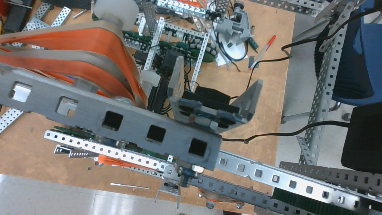
Chassis: Your chassis seems to have no good trans chassis support. I would always recommend making sure a single c or L channel runs across the entire chassis and makes direct contact with every chassis rail. The reason for this is rigidity. Your chassis is going to flex a lot without it. You can just have the chain run underneath it and rub up against the structure lightly. If you are worried about friction, give it a layer of polycarb to slide along.

What issues have you had so that we can suggest resources? Your build is quite advanced, but definitely has some opportunities.

4 Likes

Your robot looks great, did you have any problems with cubes getting stuck on the screws when collecting them? Did you file them down and/or countersink them?

I actually have 2 chassis rails running all the way across, but they’re in the back so you cant see them

Nope. It works fine.

1 Like

Is that your tray which is connected with the intake rollers? In that case how are the cubes going to come out?

The rollers are attached to rope that pull them open as the tray moves forward. I got the idea from (I think) 1727s reveal