In addition to video link in OP, anybody interested in this topic may want to check AURA’s experiment video as well as their tutorials.
To answer the question about torques, here is the graph of the force and velocity as the function of x = angle between proposed wheel orientation and the default orientation as in the tank drive (straight forward):
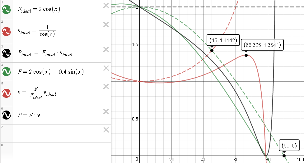
The unit of force is a single motor max (stalling) output and the unit of velocity is similarly its max (idle) velocity. In case when x=0 (tank drive) the force is 2 (two motors) and velocity is 1. Then, in the ideal case, force will drop as the function of cos(x) and velocity will grow reciprocally (dashed lines).
However, in the real world, friction, especially in the omni rollers, will make things less than ideal. As the angle (x) increases so will the friction loses and both force and velocity will start underperforming their ideal curves more and more (solid lines on the graph). Real formulas would be more complicated and I made friction coefficient high for the illustration purposes, but at some angle (x) the wheels will either slip or the friction will be consuming almost all available motor power, PTCs will be tripping, and both velocity and torque will effectively go to zero.
Note that power curves are not the real power output of the motors, since you cannot have both max torque and max velocity at the same time. Still they are useful for comparison of what you could expect from your setup.
So to answer original question I would agree with @Cody and recommend against 30 / 60 degree drive, because at higher angles it will be more sensitive to extra friction and you will be losing power fast.
But it would make a great entry for the eng. notebook to build a test chassis and measure actual forces you could get out of it. And, if you like what you get, it may work great for you.