I’m releasing version 1.00 of my smart motor library, as with all software it will continue to evolve as we learn more and test further on real robots. This library is based in part on work by Chris Siegert (aka vamfun) and is an alternative to his code posted in this thread.
The code has been tested using ROBOTC 3.51, I was hoping the next version would be out by now but it’s not. The library may need an update for 3.53 when that is released.
The functionality is as follows.
The automatic calculation of actual motor speed based on encoder value changes.
The automatic calculation of motor current based on measured motor speed and motor control value.
The estimation of PTC temperature in encoded motors and the cortex or power expander controlling them.
Monitoring of PTC temperature and limiting of motor current if the maximum PTC temperature is reached.
Monitoring and limiting of average motor current if a preset current threshold is passed.
Slew rate control of motors by controlling acceleration and deceleration.
Complete documentation can be seen here.
(links removed, it’s all on github now)
An archive with the library, documentation and examples is here.
(links removed, it’s all on github now)
The library source (no examples or docs) is available here.
(links removed, it’s all on github now)
There are still some typos and grammatical errors in the docs, I’m not much of a technical writer.
There is no support for servos in this release and the old 3-wire motors have had no testing.
I have no plans for an EasyC port, accurate timing with EasyC’s existing runtime library is a PITA.
Wow, once again, this is insanely cool. I really hope people start catching on how much this software could help their robots, and all the work you guys have put into it. I haven’t been able to test this library or the other example posted a little while ago yet due to time restraints with the robot, but once I do, I’ll send some feedback, and any improvements, if I can think of any.
Thanks for giving us this nice Library. You have saved me a lot work since much of what you have done is on my todo list. I.e. make smart monitor a #include c file, add the encoder speed code you made, give the user encoder mapping capability for multiple motors using the same speed information and fixing the 100 ms computational load by computing one motor thread per cycle.
Looks like I should procrastinate more often. Actually, I knew you were rewriting the code and I wanted to see what you would do.
I am glad you preserved most of my content including the slew rate limiter and that you made some improvements by making the current limiter function available to the user. I believe that many more programmers will take it on since the interface is friendlier and the documentation is not totally buried in the code.
A few comments:
I like that you made the target current in the presence of a cortex/PE bank trip a dynamic function of the active motors rather than using the precomputed allocation that I used. The only imporvement I would make is to give the 393’s more than the 269’s if there is a motor mix. It is not a big compromise to give them all the average since their safe currents only differ by .25 amps but this might make a difference to keeping a lift from stalling.
The simulated speed you are using when an encoder is not present is so near the i_free, why not just use I_free and bypass the speed calculations. Actually, I would rather have a slightly higher value that would represent robot accelerations being present which there usually are. As you say, it is anybody’s guess and it is just a matter of how conservative you want to be. I would error on the high by using something more akin to I_safe for the unknown motor since generally when under design load, it is close to 25% I_max.
I would like to set up some way of maintaining the standard data set for this program . Maybe create a sourceforge sw group that maintains the software under your lead.or you could provide the function. Any thoughts?
I look forward to trying the new software out and may have some more comments. Hopefully, I can chuck my software.
The slew rate limiter I lifted out of an existing library I wrote with my son last year. The original also had some non linear mapping of requested to output control values but I pulled that out for this version. It has been linked to before but it is here if anyone is interested.
We could assign a priority to each motor and use that as part of the algorithm. I did try a couple of other ways but preferred this for now, I’m also still thinking about functional grouping for the motors but it’s not a high priority, the way team 8888 usually divides motors the functional groups are often together anyway. ie. we put lift motors on the power expander.
The simulated speed assumes the motor is running at 90% of the free speed that the commanded value would create. Dropping the 90% to something lower would increase current. I wanted to do some more testing before finalizing this, my testbed robot (a 4x393, mecanum drive, pushbot) is very light and the motors run very near full speed. I need more structure so I can build it out some more and then simulate robots with different weights. The student are too busy building at present for me to have any time using their designs for testing, perhaps after the first competition I can make more measurements.
No thoughts, lets wait and see if there is any feedback. Most code I post here has very few downloads so I don’t know that the demand is really there. This exercise was mostly that I was pulling all the various scraps of code I wrote in the last few months together. I was waiting for 3.53 to be released which should have the PID control implemented, I won’t be surprised if it breaks the ability to throttle down the motors as presumably it will be creating motor drive based on encoder errors or something.
Well, that’s up to you Chris, I was not trying to replace what you had written but did want a library consistent with the other libraries that the team had.
Ok, I had some time to try the library with the trophy Bot with 2 393 HS motors.
1)When I looked at the current with motors running free it had the reverse sign and incorrect value. I traced it to a bug in the initialization. The ke = SMLIB_KE_393. It should be ke = SMLIB_KE_393/1.6 as shown in red below.
SmartMotorsInit()
{
	............
		switch( m->type )
		{
		 	........
	                case    tmotorVex393HighSpeed:
			m->i_free   = SMLIB_I_FREE_393;
			m->i_stall  = SMLIB_I_STALL_393;
			m->r_motor  = SMLIB_R_393;
			m->l_motor  = SMLIB_L_393;
			**m->ke_motor = SMLIB_Ke_393/1.6;//CDS **
			m->rpm_free = SMLIB_RPM_FREE_393 * 1.6;

			m->ticks_per_rev = SMLIB_TPR_393S;

			m->safe_current = SMLIB_I_SAFE393;

			m->t_const_1 = SMLIB_C1_393;
			m->t_const_2 = SMLIB_C2_393;
			break;

			// 269 and 3wire set the same
		case    tmotorVex269:
		case    tmotorServoContinuousRotation:
When I stall a motor, the current jumps to around 2.8 instead of 4. Not sure why this is happening. Part of it is the high value of R_SYS =.3 ohms. It seems a bit high to me. Maybe you can give your reasoning for it. It seems to me this should be closer to .14 ohms. (battery 80 mohm, low side FET 20 mohm, high side FET 20 mohm, 2 ft wire 20 mohm + ??)
any way we can see the value of c_2 in the debug which is showing 0 because of small value.
All my motors are set to torque, guess I need to switch one over.
Seems like the 1.6 factor may need to be incorporated somewhere else. I will look into it.
Edit:
Ok I set a 393 into high speed mode, made the change to fix the bug you found and tried stalling the motor. Calculated current is about 4A which is in line with what it should be per the calculation. My battery drops to about 7.2V when I stall (needs charging). The 4.8A max current is rarely ever seen, perhaps with a cold motor the first time it is stalled, but even then for less than 1 second.
I used a hall effect current sensor and compared its output against calculated current. This value seemed to be the best compromise when I was working on this post.
Thanks for the feedback, there are a couple of other minor bugs but I was waiting to release 1.01 until after the ROBOTC PID is implemented as that will break everything anyway.
Rats: put a charged battery in and a motor controller 29 fried. Anyway a few more comments.
1)I think the 2.8 was with a very low battery. I used the charged one and saw 4 plus amps with stall.
I found it easier to group the dynamic variables declaration so it would be easier to view on the debug screen without scrolling sometimes. Perhaps you might want to incorporate this slight reordering:
typedef struct {
	// the motor port
	tMotor      port;

	// copy of the system motor type
	TMotorTypes type;

	// due to alignment we get a free variable here
	// use for debugging loop delay
	short       delayTimeMs;

	// pointer to our control bank
	smartController *bank;


// variables used for current calculation
	float   i_free;
	float   i_stall;
	float   r_motor;
	float   l_motor;
	float   ke_motor;
	float   rpm_free;
	float   v_bemf_max;

	// current limit and max cmd value
	short   limit_tripped;
	short   limit_cmd;
	float   limit_current;

	// the encoder associated with this motor
	short   encoder_id;
	// encoder ticks per rev
	float   ticks_per_rev;

	//// variables used by rpm calculation
	long    enc;
	long    oldenc;
	float   delta;
	float   rpm;

// commanded speed comes from the user
	// requested speed is either the commanded speed or limited speed if the PTC
	// is about to trip
	short   motor_cmd;
	short   motor_req;
	short   motor_slew;

	// holds safe current for this motor
	float   safe_current;
	// target current in limited mode
	float   target_current;

	// instantaneous current
	float   current;
	// a filtered version of current to remove some transients
	float   filtered_current;
	// peak measured current
	float   peak_current;


	// PTC monitor variables

	float   temperature;
	short   ptc_tripped;

	float   t_ambient;
	float   t_const_1;
	float   t_const_2;

	// Last program time we ran - may not keep this, bit overkill
	long    lastPgmTime;
} smartMotor;
I was thinking about why .3 R_s was the best compromise. Perhaps it was because there was actually an extra voltage drop caused by the added current draw from the other side of the cortex when you were testing. The circuit has some added dependencies which are not modeled. In addition, the big series resistance of the battery (80 mohms) is upstream of where we measure the voltage so the remaining series resistance would be around 60 mhoms. Someday I will redo the equations which will use numerical integration instead of the closed form which assumes that the measured voltages are constant.
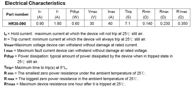
I think it may be simpler than this. The current model that I (we) are using does not account for the resistance of the PTC as part of the current calculation. Current feeds forward to the temperature calculation but the increased resistance of the PTC does not feed backwards. Here is some typical data from the HR30-090 datasheet.
[ATTACH]6933[/ATTACH]
It has a minimum resistance of 140mΩ and 1 hour after tripping is still up at 350mΩ. We may be able to add this into the model but it still leaves the problem of what to do for the initial condition when we have no knowledge of the motors starting condition.
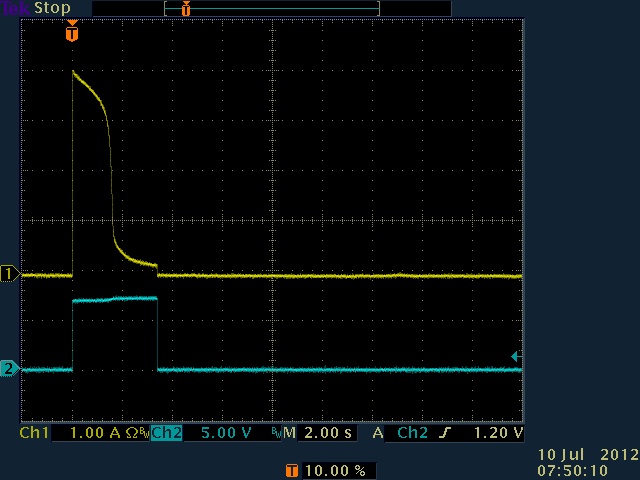
Also FYI, here is an old scope trace showing stall on a 393 motor and how quickly the current drops.
[ATTACH]6934[/ATTACH]
The current is only ever up near the 4.8A maximum for a very short amount of time (in fact this trace shows a maximum of around 4A as the motor had probably been previously tripped). My recollection from when I was playing with the algorithm back in October was that I was more focused on smaller current estimates around the 1A mark rather than near stall. I also found that the model is very sensitive to the value for maximum rpm, and Vbemf calculated using Ke derived from this, and sort of concluded that unless the parameters were tuned for each and every motor there was always going to be some inherent error.
Anyway, thanks for pointing out yesterdays bug, at the time I tested this all my 393 motors were installed on a chassis and I didn’t want to pull one out to change gears. I have more motors now so it’s not as much of a problem
Dooh!! You’d think I would have thought of this after all the time I spent modeling the PTC resistance vs temperature. Anyway, I wanted to review what assumptions were made in my motor model and how the PTC’s might be properly incorporated. See this post:
After you review it, lets agree on what changes should be made to the current model.
This update is to fix the bugs found to date and make it compatible with the V3.61 beta that was made available over the weekend. Although compatible, if PID is turned on then current and temperature for the PID enabled motor will not work correctly, I will provide a more comprehensive update when 3.6X is finished and it’s possible again to intercept the command value going to the motor. If PID is not used then it should behave the same as before.
Here is the change log.
bug fix to SmartMotorLinkMotors, master parameters not copied correctly.
bug fix for High speed 393 motor initialization (from post #6)
kNumbOfTotalMotors replaced with kNumbOfRealMotors to remove warning about signed/unsigned comparison. As there are no virtual motors on the cortex these are the same.
Target_Emulator used instead of (_TARGET == “Emulator”) so as to remove warning about ANSI C compatibility.
tmotorVex393, tmotorVex393HighSpeed & tmotorVex269 enums have been depreciated in V3.61, replaced with new versions.
Pointers are not the issue, EasyC supports pointers better than ROBOTC.
It could be ported, all the ROBOTC specific code, things like using the motor] array, would need converting and obviously EasyC does not have tasks. There are problems in detecting what the motor types are as well as the all of the unneeded “wait” calls that EasyC puts in things like LCD display code. One day I may rewrite the whole runtime library but until then I’m not particularly motivated to port it.
I posted a minor update to the smart motor library.
Change log.
Version bump to 1.02
Added new field to smart motor structure to simplify motor linking.
Changed SmartMotorLinkMotors to correctly link the slave encoder motor port to the master encoder port if the encoder has not been assigned in Motor & Sensors setup.
How’s that going to work? The encoder is used to measure the actual speed of the motor, a potentiometer cannot measure the speed of a continuously rotating device.
Consider the situation where you have a motor operating an arm. If a program is telling the arm to lift more weight than it can handle then the motor will stall and the PTC will heat up. The program should make up for this and cut down on the amount of power put to the arm motor.
The potentiometer can be used to tell how much the motor has rotated just the same as the encoder, it just cannot rotate past ~270 degrees.
It would be a simple conversion to RPMs which it seems like your algorithm uses as the base unit for determining temperature of the motor.
Please correct me if I’m not understanding how your library works. I’m a decent programmer but the guesstimation of temperature is totally beyond me.
Yes, that could be made to work. Accuracy may be down compared to using an IME (which is what the library really wants) but it could be done. The change would only affect the SmartMotorSpeed function along with the necessary flags or whatever to store the fact that a pot was being used. Gearing between motor and sensor is already handled. So thinking about my Z teams robot, we had about 1820 counts on the pot between arm low and high, that’s about 90 degrees. We had 8.33:1 gearing so about two turns of the motor. ticks per rev would be 910, actually not too bad. I will throw it into the next version (whenever that is, I don’t think many people are using this anyway).
We have vamfun to thank for the PTC math, I generally prefer to use it in the simpler current limiting mode,