<R11>… The intent of the rule is to allow teams to purchase their own commodity hardware without introducing additional functionality not found in standard VEX equipment. It is up to inspectors to determine whether the non-VEX hardware has introduced additional functionality or not.
So I may need to clarify what qualifies as a additional functionality. the GDC has confirmed that any commercially available bolt can be used, including set screws and screws with captive washers, …
… but not threaded rods or eye bolts. However this is spread across the last 5 years worth of Q&A.
While I love this design, I am left to ask if the thread free part of your screws introduces functionality not found in standard vex hardware. If the functionality is limited to “gear spins on it” then is a better spin additional functionality, or just superior functionality. I think this should be dropped into an official Q&A, because I would love to know for sure with this added clarification.
How would you differentiate, as an inspector, between a bolt manufactured with a longer unthreaded section, and a fully threaded bolt with the threads carefully filed off to the desired location?
I would recommend more clarification from the GDC. However, the rules allow for larger bolts, like , which could be machined down to the appropriate size, increasing the cost and exclusivity, which is counter to what I believe the GDC has in mind for this rule.
Theoretically a student could chuck some high strength shaft on my metal lathe and turn most any fastener up to 12" long and 1/4" diameter. I’d have the students take pictures to prove the material came from legal VEX parts.
How good is the high strength shaft material for bolts? Vex lists the material type as 1018 steel, but I am not very familiar with the various types of steel
1018 is a pretty typical low carbon steel for non-heat treated fasteners and stuff. The “10” means plain carbon (no alloy) and the “18” means 0.18% carbon.
Congratulations on creating the transition system for the gear set.
Would you like to know more details about this construction, do you have images with more details of the construction or some 3D drawing that could be shared?
This looks very solid, however, I have a few questions about it. Is there any reason why you put a gear on the bottom bar, and is there a benefit to not stacking the two mid-gears? Also, wouldn’t it be sturdier to sandwich the bars connected to the tower rather than attach them on one side?
I’ve seen people using partially threaded screws in VRC for years. And that would be perfectly consistent with the original wording of <R7c> which became <R11> this season:
<R11> Certain non-VEX screws, nuts, and washers are allowed. Robots may use any commercially available #4, #6, #8, M3, M3.5, or M4 screw up to 2” (50.8mm) long (nominal), and any commercially available nut, washer, and/or spacer (up to 2” / 50.8mm long) to fit these screws.
The most relevant official Q&A that makes such screws legal is this post from May 2013:
I would love to, but RECF & GDC made it especially hard for people to ask questions in the new Q&A format - I will not be able to do this until the fall in the earliest. They are likely to miss a bunch of useful questions that could help them make corrections and clarifications to the game manual early in the season.
Also, I just realized that you cannot search Q&A from multiple seasons with the new interface. Forum based Q&A format worked so much better in so many different ways.
We found that you can polish screws with a buffing wheel to smooth out the sharp edges. It takes off only a few thousands of an inch, retaining all functionality of the thread.
On the picture below, the middle section of the top screw was buffed and if you look closely you can see round thread profiles compared to sharp triangular shapes on the edges or unmodified bottom screw:
If you run lift gears under light loads, you can hardly notice any difference from the the partially threaded screws. Starstruck was the only season where we saw loads on the screw joints large enough to damage the plastic bearings. But that would take several competitions before you would need to replace the shoulder bearings.
Partially threaded screws would be great to have if we could, but it wouldn’t be the end of the world if we couldn’t. Although, it saves a lot of work that needs to go into uniformly polishing each screw.
I think that if a piece of hardware that was ruled legal in the previous seasons could be easily bought in most of the local hardware stores at the very affordable price, then there is no good reason for GDC to suddenly make it illegal.
You could build most designs without partially threaded screws, but I found over the years, that having two (regular and smooth) screws on the palm of my hand is a great conversation starter to talk to students about axle friction and how it impacts the operation of their robot. It is a great visual aid for the teaching, if nothing else.
The gear on the bottom bar is there to make structure more stable and have symmetrical (pure torque) load on the pinion 12T metal gear driven by the motor. You can even get away without supporting its axle on the other end (maybe).
I am not sure what you mean by stacking.
Finally, as far as I understand, sandwiching the bars is not necessary with the long screws and will only make construction of the mid-section more complicated.
This particular prototype was designed to provide maximum stability with the minimum number of parts. In theory it could operate one sided for small end loads, but if you want to carry several cubes at once for Tower Takeover game that is, obviously, not recommended. You got to build both sides.
I mean putting the top gear directly over the bottom gear. I have never seen a team mount the top gear slightly forward so I was just wondering if it provided any benefits.
Well, I’m sure it allows for a tighter and more consistent meshing of gears, preventing (or trying to prevent) slipping.
As a team with a box of stripped gears(from before I found other solutions to increase build stability and quality), I’d appreciate that.
A standard DR4B has the vertical motion of the top most linkage and the bottom most linkage in a vertical line. That means you need to have them move past each other. With the offset, this problem is solved, as the top most linkage is now horizontally in front of the main towers, which frees up space to build your flip down manipulator and makes it easier to have your axles and bolts move past each other without hitting while moving up or down.
@Anomalocaris, that is a good observation about the top gear being offset forward - there are multiple reasons for that.
As @AperatureLabs correctly pointed out, the main reason for the offset gear was to move top bars forward such that their top/forward joints could be fully in front of the tower.
Also, splitting mid-section in two, allows precisely adjustment of distance between the gears (@Got_a_Screw_Loose got it right), improves its structural rigidness, and makes it easier to build entire DR4B in two separate pieces and then assemble them together.
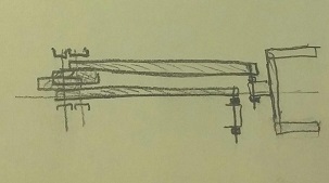
The focus of the original DR4B post was to show how long screws in the joints could improve stability and precision of the DR4B lift. I wasn’t going to talk about the other features of that prototype until it could be tested with the real game objects…
Other goals were to see if you can build a stable tall DR4B with minimum number of custom cut parts and easy assembly. I am curious to see if such lift could be stable with just one side and that calls for all joints to be as close to the centerline as possible:
I am actually thinking about adapting your offset design into my robotics class as a build after the clawbot, since it is so simple to understand and recreate from the pictures. In your experience, do you find it more reliable/simple to use arm-mounted or tower-mounted motors?
I couldn’t think of any reason that would once and for all decide if motors should be mounted on the towers or mid-section of the DR4B. There are cases where either of the methods could have more advantages.
If the design calls for two DR4B motors and dual towers, then it could be easier to mount motors on each tower. For a single tower design, you could put one motor on the tower and another on the mid-section.
Having dual motors mounted on the mid-section could also make it easier to mechanically connect the pinion gears on the left and right sides of the lift to ensure it doesn’t lean to one side.
In this specific case, where DR4B will have just one (V5) motor, it makes sense to put it on the mid-section. It will need one less 60T gear and will be 1" more compact in the horizontal dimension.
If the lift is properly rubber-banded the effect of the motor’s weight is not that significant compared to the weight of the intake and the game object(s) on the end of the lift.
Finally, for the more advanced designs, where you want to use dual motors in the differential configuration (like @ZachDaChampion of team 77788J did here ) then placement of the motors will depend on whether you want to send secondary function power down toward the chassis or upward toward the top of the lift.