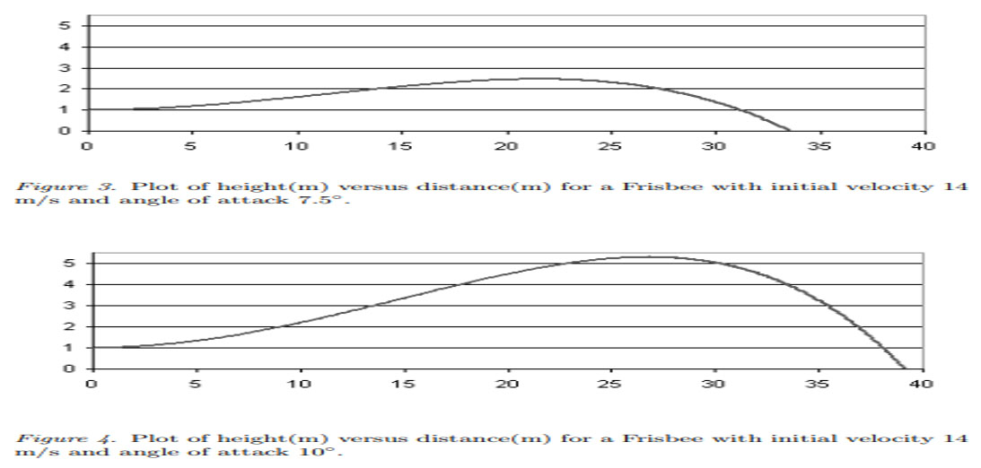
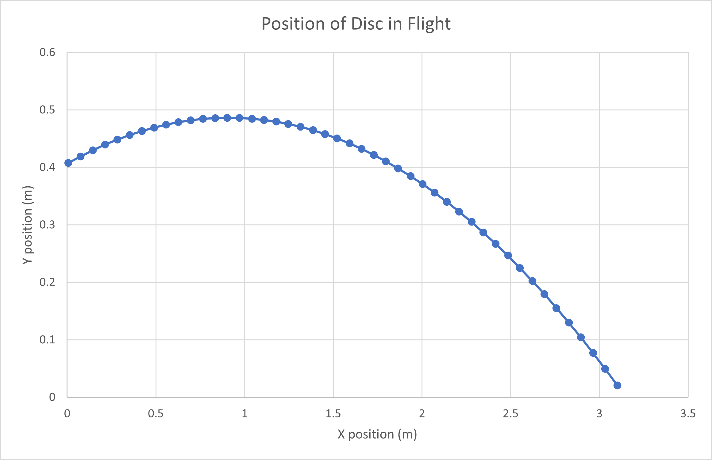
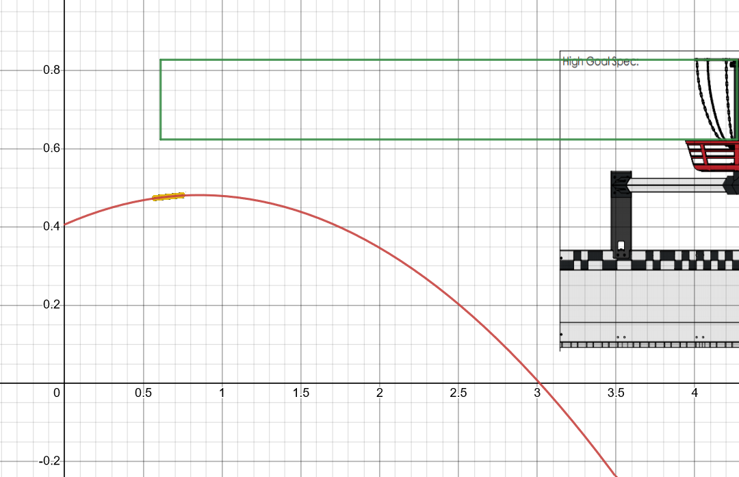
The path curves upward over the distances that are required for this game. To be honest, the problem of hitting the goal this year is much easier than NbN or TuP, because the target is vertical and the flight path is near flat. The same launch angle and velocity should work over most of the field, since the disc can hit the goal low or high and still score.
You can use same basic trig to figure out the range of angles a shooter would have to be at every distance away from the goal. If you find the angle with the greatest overlap then that would be the most optimal angle. Now, some things to be considered for this.
First, trig assumes perfectly straight flight paths. Second, the MIT diagram assumes an initial velocity of 14m/s. I would think that the discs we will be launching will be much slower. If we are launching them much slower, than the end of the curve may start to have an effect, especially when launching from opposite ends of the field. I think this can be seen in the Purdue Ri2D.
The article provides code for solving the trajectory.
Not so sure that 14m/s is unrealistic for vex parts. Just spitballing, the sigbot prototype uses a 4" compliance wheel at what looks like 4200 rpm and stretches out significantly from centripetal force. Assuming it is 5" diameter when spinning, that is .399m circumference moving at 70 rps = 27.9 m/s. Of course, the flywheel will not impart all of its velocity, but >14 m/s is probable.
Good to know, I hadn’t done the math. If it was going that fast, I would have expected the disc launched in the video to appear to travel more straight. It might also have something to do with the fact that we are launching symmetrical discs (between the top and bottom half), and not frisbees. This would mean that the aerodynamic affects on our discs would be different then that of a frisbee. The java code may have a way to address this, I have not looked at it.
This post. This post will likely be my favorite post all season. This is what I believe the forum is best used for. For users to teach and to learn. This is an incredible tool and I wanted to thank you for creating it and posting it here.
Would you be willing to take the time and write out your work and add it onto the OP? Maybe hide it in a spoiler? I think that would be an incredible learning opportunity for someone who has not taken a physics class to understand how the math relates to the physical world.
However, it is also important to keep in mind that if you were to transfer all of the momentum from the wheel into the disc, then the disc would stop moving. You actually do not want to transfer that much energy into the disc. If you transfer too much through the compression of the disc or wheel, it will put a lot of strain on the flywheel motor to re-spin up the flywheel.
It is not a matter of transferring velocity, but rather transferring momentum.
Would you mind elaborating how you would transfer momentum as opposed to velocity? I haven’t dealt with flywheels, but I’m having a hard time imagining the difference.
I want people with discs to just go ahead and start gathering data. These discs don’t have the bodies of Frisbees and are symmetric on top and bottom, so they are going to fly quite differently.
I am curious about this as well. As I understand it, most of the lift is due to the angle of attack / launch angle. There are throwing rings that do not have an airfoil cross section, but they surely fly.
I am referring to the fact that just because the flywheel is moving at a certain tip speed, does not mean it is possible to get the actual frisbee moving at that speed. You are creating rotational velocity, with some of the energy from the flywheel, as well as propelling it forward. Additionally, the more energy the flywheel imparts on the disc, the less energy the flywheel will have. This means that the flywheel will be moving slower making it harder to spin up.
The actual physics of a frisbee are quite complicated, and rotation definitely does play a role in it (I don’t know that much about it). But frisbees are known for being slow moving and traveling far distances.
This is a great post and coming from someone who actually plays disc golf, I can appreciate the information that is being shared! I would also mention that you might have to consider any environmental factors that might be going on in the location of the comp and will affect your disc flight, especially since they are foam. Not saying there will be massive headwinds or tailwinds, but the build design could also aid or deter in rotation, velocity, or stability. In real disc golf, rotation is also your friend for keeping a disc aloft , wobble on release is bad because it affects flight, and velocity can shoot your disc through the chains or possibly bounce the disc off the chains. Those basket chains look rather far spaced apart from what I saw. So much to think about! Good luck everyone!
the problem with that kinematic equation is that it doesn’t account for air resistance, which according to my roommate who is an Aerospace Engineering major, is an incredibly difficult thing to account for.
It is not only the air resistance, but also the way that lift and the other aerodynamic effects come into play when launching a spinning disk. Although I believe the MIT paper I posted above does a good job going over everything.
I rewrote my math, highlighting the formulas and methods I used to derive the final equation. It is all scanned and put in a collapsed text box under the edit.
While I think this is a really useful tool bc how air resistance and lift and spin on the disc work it would be very complicated to figure this out without trial and error. Even if you figure out a “vector” for this to work with you also have to think about your x and y vectors while you are moving your robot around.
I added a small feature to adjust the graph based on the robot’s movement. “Rv0x” refers to the robot’s velocity toward or away from the goal. This value adds to the initial velocity of the disc and works as you would expect: When Rv0x is greater than zero, the goal moves faster and arcs further. When Rv0x is less than zero the opposite happens.
Here is a new link to the graph. I’m not certain how Desmos handles sharing so this link will definitely have the new feature: Spin Up Launch Analysis | Desmos
AP exams
I think they went well. I took AP Physics C (Mechanics and Electricity and magnetism) which was really intense. Most AP exams that I’ve taken are a college semester taught in a year in high school but this course is 2 semesters in 2 semesters. There was a lot of course material but I’m glad I took the class.
I have modified the code in the MIT paper and ran my own simulations based on it. I want to point out that at lower speeds (about 5 to 7 meters per second), and no angle of attack a parabola does model the flight of the discs that will be used in this years game. Based on my incredibly rough estimations, I took from the Purdue reveal, they appear to be launching the disc at about this speed. Additionally, the purpose of the MIT paper, is to model the changes in angle of attack. Just to clarify, and as stated in the MIT paper:
α is the angle formed between the plane of the frisbee and the relative velocity vector
In other words, it is not the launch angle. The launch angle can be determined by the X velocity vector and the Y velocity vector.
Below is a comparison of the MIT model, which I modified, and the kinematic model posted by the OP:
These are the constraints placed on the disc:
Initial Speed: 7m/s
Launch Angle : 10 degrees
Launch Height: 16 inches from the ground
Angle of Attack: 0 degrees
As you can see, with an Angle of Attack of 0 degrees, the two graphs are remarkably similar. This is because the Angle of Attack of the disc is the primary way in which aerodynamic affects would cause additional lift to the disc. Therefore, without this, the disc does behave remarkably similar to a point mass as assumed in the desmos model.
In addition...
I plan on creating a more in-depth forum post/video explaining everything I did to the MIT code and, doing a more in-depth explanation of the physics behind this all. I am super busy with school right now, so if you are interested in that please let me know. That will probably not come out for another couple of weeks. I can not promise that I will do this but I will try.
Also, yes I am aware that 1 model is a very limited sample size for something like this. Hopefully, if I make a video I can give more in-depth comparisons and results.
If there is interest, I am also open to sharing the modified code.
In Summary:
The OP made a very good, and simple to use model.