You are correct that a typical launcher, regardless of the launch angle, will have effective initial angle of attack of zero. But as the disc starts to loose the vertical component of the launch vector (due to gravity), the angle of attack will gradually increase, adding lift.
So my intuitive expectation is that while the disc will initially follow parabolic trajectory, it greatly extend the “apogee” with longer segment of level flight.
There is a bit of conflation of launch angle and angle of attack in the launcher I think we are all vaguely visualizing: a tilted plane with a horizontal flywheel. A disc released from that launcher will have a Y velocity and and angle of attack related to the angle of the launch platform. This means that there is some additional lift due to angle of attack.
To describe the flight paths plotted in the MIT paper, they open with
When conducting the simulations, all trials had an initial height of 1
m, an initial x velocity of 14 m/s which is considered that standard
velocity of a thrown frisbee, and an initial y velocity of 0 m/s. Trials
were conducted using angles of attack ranging from 0◦ to 45◦.
So, in the graphs I linked above ALL of the lift was from angle of attack. Their model has a launch angle of 0 and an attack angle of 0-45 degrees.
I agree that @TheRichDarth has provided an interesting and useful tool for initial design. However, your re-running the model without angle of attack and noting the disc behaves like a point object is not considering what is actually happening. The disc does have and angle of attack, and it must be factored into any model that attempts to describe its flight.
What would the angle of attack be for a disc launched from an inclined flywheel?
My confusion stems from this:
If the plane where the disc is being launched from does not have an incline (by no incline, I mean no incline relative to the force being imparted on the disc) I would think that initially there would be no angle of attack because the angle the disc is making with the horizontal, is the same angle as that of the velocity vector. As time goes on as @nenik pointed out, an angle of attack will develop. This I did not factor into my model, but I hope to in the future.
From Purdue’s RI2D, on all videos of the frisbee moving through the air, the angle of the frisbee changes negligibly, thus the angle of attack of the frisbee needs to continually change to match this. I have no idea how this will work on actual foam disks, but I expect the behavior to be similar.
I don’t think this helps to reduce the confusion, so let me try to spell this out differently.
The angle of attack is the angle between the disc vector of movement and the disc’s plane of rotation.
For a typical flywheel launcher shooting at, say 15deg angle, the disc’s plane is initially tilted 15deg up, but it is also initially moving at 15deg up trajectory. That means the initial angle of attack is zero and the disc provides no lift.
Without the lift, the disc initially moves on the parabolic trajectory, loosing the vertical component of the velocity vector due to gravity. Thus, the velocity vector changes from 15deg towards zero (and ultimately below). But the plane of rotation, due to gyroscopic effect stays pointing 15deg up. As a consequence, the angle of attack keeps increasing and the disc will get some lift (but also more drag, slowing the disc down on horizontal axis), flattening the flight for some time.
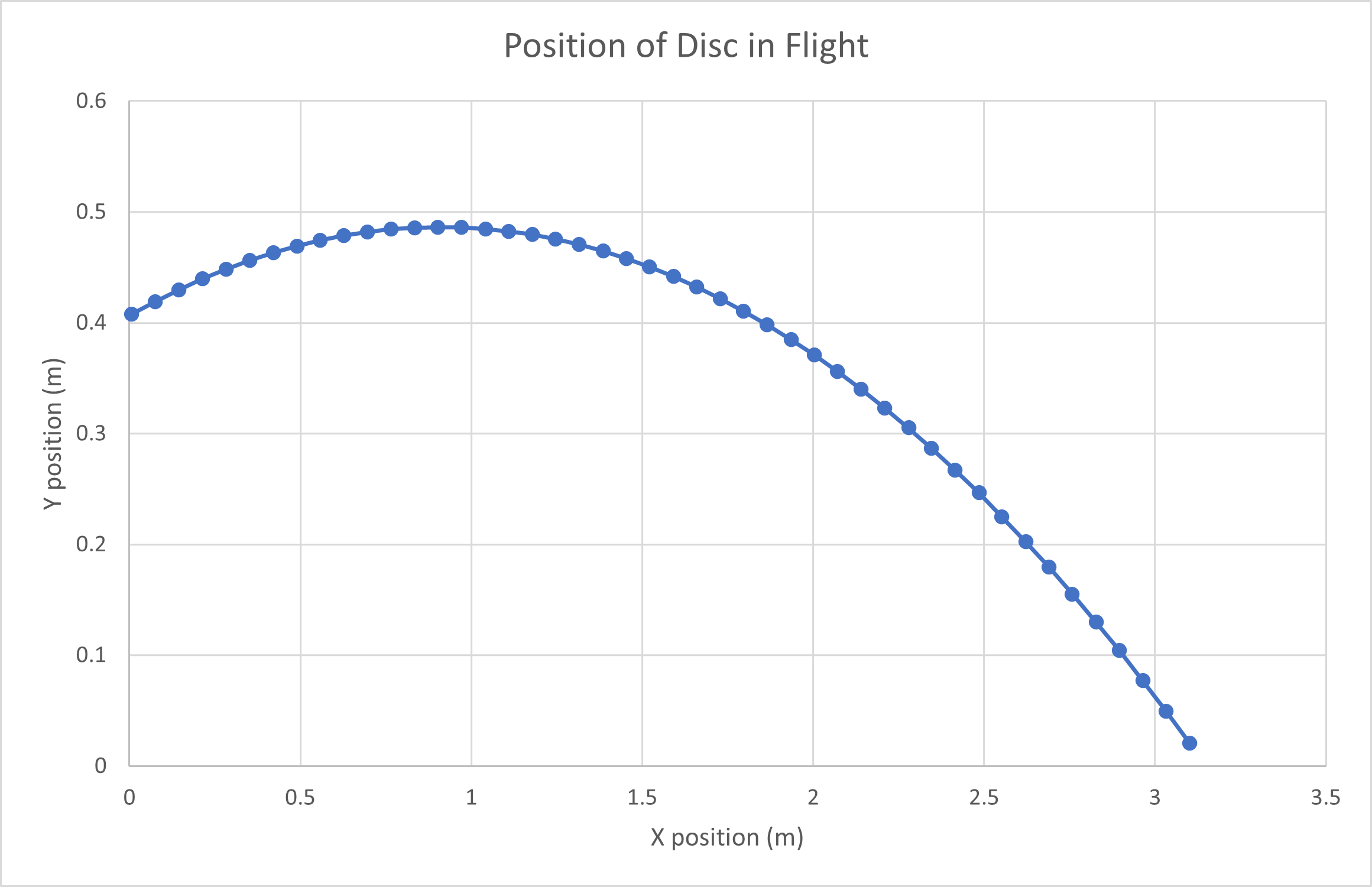
I whipped up some quick simulations in Khan Academy, and it seems that the frisbee reaches a highest point, and then drops. This is unrealistic, as the frisbee would start moving backwards at the peak, but I believe the rest of the model works fine.
To clarify then, all it would take in order to make the model more accurate is to, re-calculate the coefficient of lift at every iteration, with a new angle of attack. With the angle of attack being equal to the difference between the initial angle of attack and the current angle of the velocity vector. Edit: the drag would also have to be re-calculated.
Am I thinking of this correctly?
Also, I wonder, why the original MIT model would not have included this.
I think one thing we all must remember is that the MIT paper is only a good approximation for certain conditions. If one threw a frisbee at a really high launch angle, eventually the frisbee starts curving backwards, I don’t think the MIT paper accounts for this. Also, the MIT paper does not account for all the moments acting on the frisbee because of its spin, drag that occurs because of spin, or any 3D forces that occur when the frisbee is not launched at a 0 degree tilt in the Z direction.
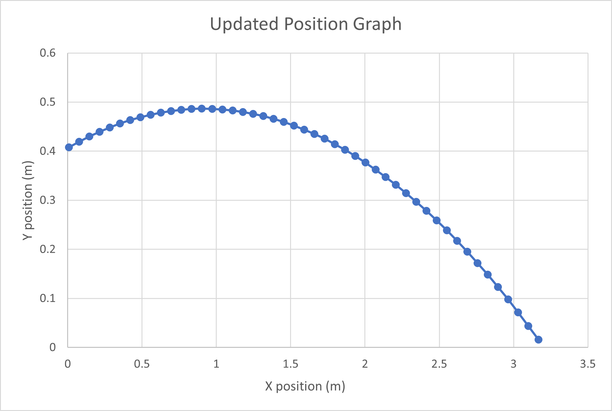
I re-wrote some of the code. This time I re-calculated the lift coefficient and drag with an updated angle of attack. The output I received is very similar to the original.
One more thing, my simulation for the frisbee that varies the angle of attack can be found here:
It’s a pretty simple remake of the Java program in the MIT paper, I did not change any of the lift or drag coefficients, so I’m sure the actual data is wrong, but the flight pattern in general is correct
If you are only varying the angle of attack, and not the launch angle of the frisbees, that is not indicative of how most flywheels work. For the flywheel on the Purdue bot (and the others demonstrated on youTube), there is no initial angle of attack, even though the mechanism is pointed at an angle. This is because the angle of attack is the difference between the angle the disc makes with the ground and the velocity vector.
I have the angle of attack calculated based on the difference between the original launch angle and the heading of the velocity vector. In my program, the launch angle is what can be changed, and the angle of attack is calculated based on that.
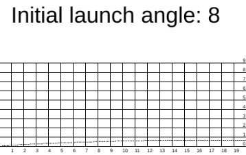
I put the velocity at 7 m/s and the launch angle as 8 and got this:
I guess I’m figuring those are feet along the axes, because that’s a lot of meters. That looks like a really flat curve.
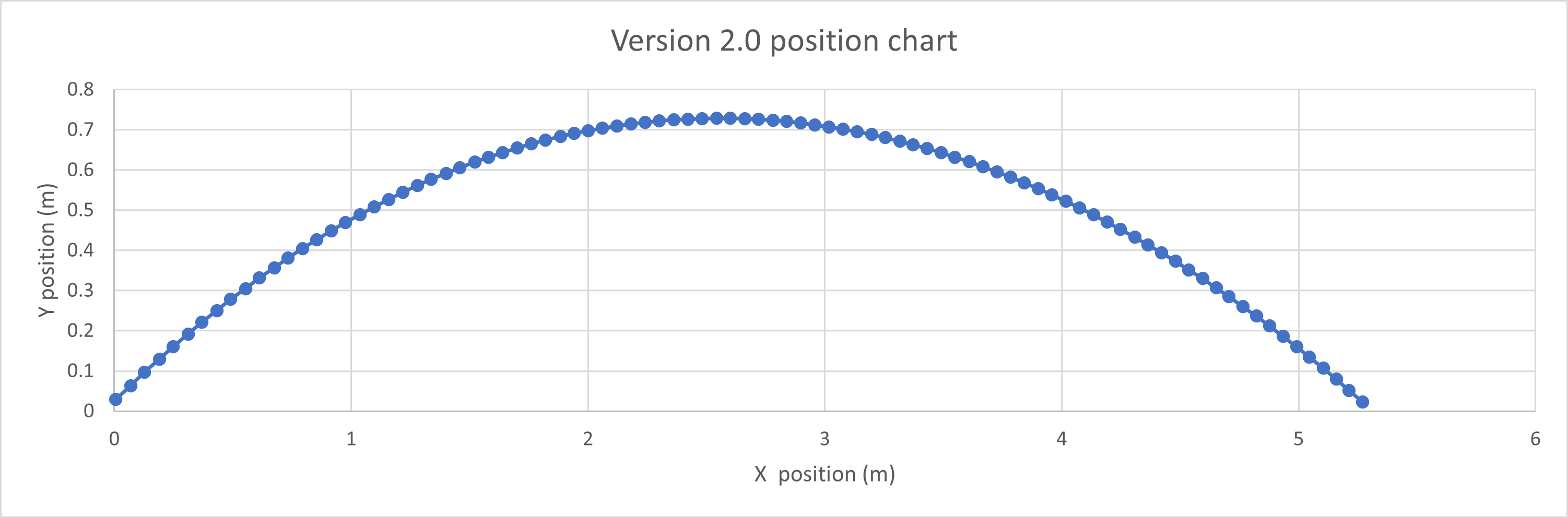
After a lot of messing around and adjusting of values, I realized the discrepancy. I had some bugs in my code, but after looking at it some more I fixed them. I want to say thanks to @46X for his code because it helped a lot. The reason the shape of the graph’s differed was because of a discrepancy in the value for the cross-sectional area of a disc. There was a larger value for this constant in the code on Khan Academy, meaning that the aerodynamic affects were getting multiplied by a greater value than they should have been.
I’m assuming it’s the lift coefficients being the same for a normal frisbee coupled with the lighter mass of the vex frisbee causing way more lift than is necessary.
When the mass is returned to the original value in the MIT paper, it only moves about 1.5 meters at 8 degrees.
Edit: Thanks to @LastMinuteFix for also noticing that the area of the disc was 5 times higher than what it should have been.
I am attaching a link to a GitHub repository with my code in it if anyone is curious about the particular method I took in modifying the code presented in the paper.
新起点机器人实验室 (New Starting Point Robot Laboratory) has recently gotten started on building a robot for this year’s game. While the video does not show the robot at all, I think that it should give some ideas as to how the discs will fly in the air.