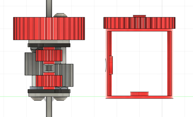
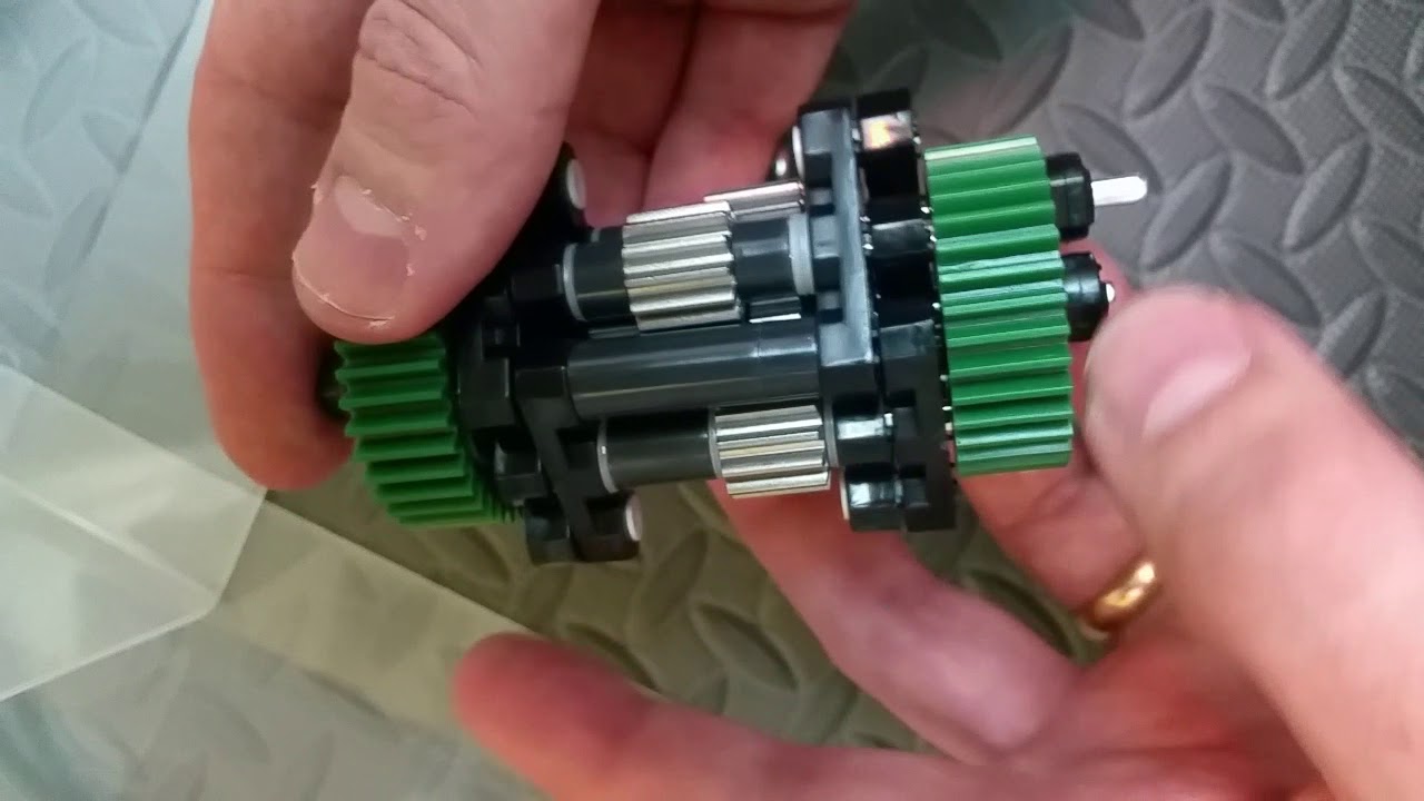
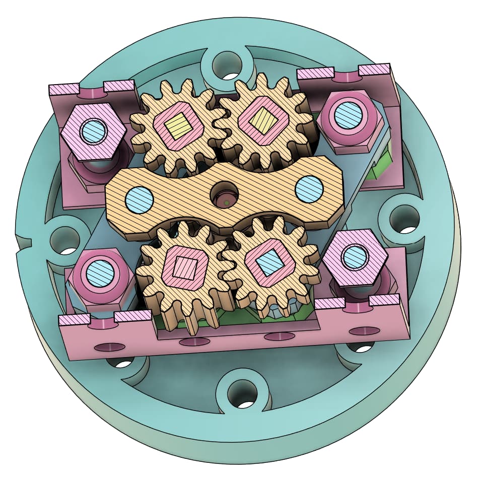
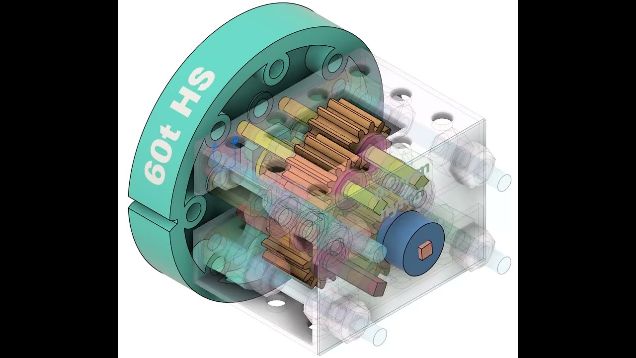
Since many of us (including me) responded to your poll with: “I don’t know how straight teeth diff work but I know what is a diff,” it would be helpful if you could explain how the mechanism works (especially if the image you provided is from a 3-D model you made/ have access to).
I know we could all individually scour the internet for an explanation, but it would be even better for as detailed of an explanation as possible to be here for future reference, especially for users who might find this topic through the search feature later on.
The easiest way to understand how a differential works is to hold the carrier (the piece that holds all the gears and spins around) still and look only at the two output shafts.
A “standard” bevel-gear differential relies on the fact that two bevel gears on opposite sides of a single bevel gear can only spin in opposite directions.
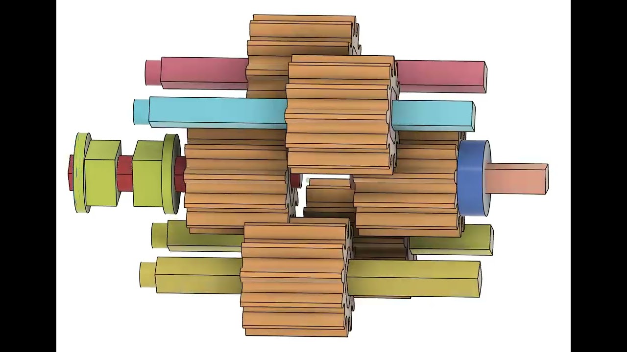
A straight-gear differential relies on a rather clever trick: each of the “center” straight gears mesh with the other “center” gear and ONLY ONE output shaft.
If you hold the carrier still and turn the “top” shaft clockwise (looking down from the top), the following will happen:
The top shaft will turn the “output” gear attached to it clockwise
The top “output” gear will turn the left “center” gear anti-clockwise, since it meshes with one end of the top “output” gear
The left “center” gear will turn the right “center” gear clockwise, since it meshes with the other end
The right “center” gear will turn the bottom “output” gear anti-clockwise, since it meshes with the other end.
If there was a single gear connecting the output shafts, they rotate in the same direction if the carrier is held still (exactly wrong for a differential).
The fact that there are 2 meshing gears, each connected to only one of the output shafts forces the shafts to rotate only in the opposite direction if the carrier is held still, serving as a differential.
Very clever use of standard and high-strength gears, @Lao6.
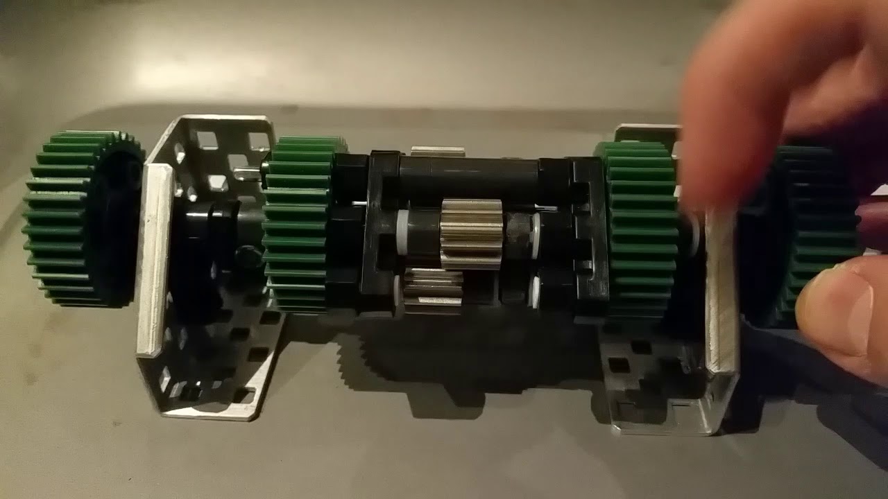
After reading your post and doing a bit of digging online, I realized that I was for some reason operating under the misconception that there wouldn’t be planetary motion of the whole mechanism in this design. This video helped me realize this visually (see the end - where it’s spun while in a carrier). I now understand how the system works (great work @Lao6), so if anyone is still confused, I recommend giving the aforementioned video a watch-through, especially if you need to see it in motion to understand it.
I freehanded these a few years ago, so there’s no CAD:
IIRC I was intending my next step to be to add strength in torsion between the framing gears to stop the axles gripping in the bearings. It was sticky despite all the teflon washers.
It didn’t see action on a robot - I was just playing with ideas to work into mentoring. You’ve flagged some of the basics to some extent, and there’s more or different design work to do before my version is any practical use, I think.
'Tis hard, using the words, and finding the phrase that makes the words work together is hard, words on their own can mean one thing, words working together can mean something else"
Turns out I CADded a diff with a frame, but this hasn’t been built never mind tested. This reminds me that the smaller one has dremelled bearing flats like you can see here.
I’m glad you like it
More generally to the crowd:
Read @teresajude 's explanation.
The wikipedia entry for differential gears is pretty good Differential (mechanical device) - Wikipedia
Watch the .mov @Lao6 found above.
Here’s a more exposed view of the spur gear motions in my CAD. I’ve included a clue pointing to a potential alternative scheme for mounting the pinions.
My inputs aren’t answers to the problem - they’re just illustration of stuff that can happen, and you need to find what works for you.
A lot of folk seem to ask for the “best” way to do something, whereas - especially in competition - you need to find something good for you by trying alternatives and variants. The importance of fumbling around in the dark a bit can’t be overstated. That you don’t have the answers yet means that you can’t see them yet, and when you do see them, your first impressions will be incomplete. Where’s Wally? How many wallies are there? You don’t know yet.
There isn’t even an undisputed, universally best way to move sideways, for example.
And don’t forget there are actual rotational bearings now. They’re quite chunky, but a diff can be as big as it needs to be.
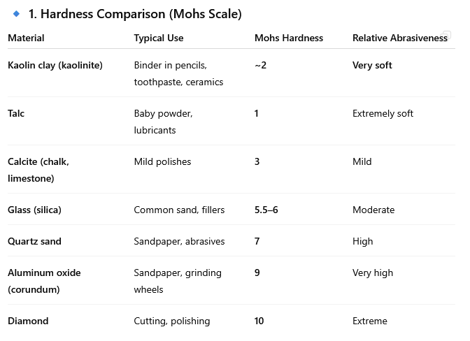
Be aware that pencil lead contains abrasive clay that will help rotating elements grind through their mountings. As for graphite, consider that conductive particulate matter is bad news for connectors and electronics.
A tiny dab of lithium grease that escapes will just join the general sea of finger grease already covering your robot and its wheels. Clean your robot, and especially wheels/rollers and surfaces they have to climb on the field.
Differentials have things spinning within a spinning thing and so can distribute loose material far and wide.
Build to run as freely as possible without grease. Grease in the amounts allowed by the rules doesn’t create freedom of motion, it takes the edge off friction.
Think about how fast or slow various parts of the differential could rotate in relation to the mechanisms they’re attached to - you get to choose/design those speeds.
First, I had forgotten that pencil lead does contain a clay binder.
Second, I’m not an abrasive expert, but from using pencil lead in a bot that sustained a lot of use and heavy loads… there was no noticeable wear/polishing on the aluminum (was used on a sliding mechanism), so by gut said that it’s not a problem… at least under limited use that a robot will see. I probably wouldn’t use it in industry for a long time.
Powdered graphite is presumably ‘pure’ but a heck of lot harder/messier to work with.
As far as conductivity goes… this would actually be a good thing. Let me dive deeper. I’ve seen some bots have problems with motors on arms/lifts frying. I bought a static electricity meter and learned that bots can generate a LOT of static (I posted on this here).
However, if a team is using plastic/nylon bearings, parts of the bot can be electrically isolate, build up a differential charge, and eventually get enough static charge to fry components. If graphite (or a grounding connection) bridged this gap… it would let the charge bleed off and avoid killing parts. We performed tests on this.
That said… I wouldn’t want graphite in my brain’s connectors.