If my math is correct, the maximum score is 45 points. This means you get all 9 bonus points and steal your opponents doubler barrel. you also need to use each doubler to double a stack of 6 scoring objects. My breakdown was:
There are twenty-two objects total.
18 points from nine objects. (first object in all nine goals)
5 points from adding 5 objects to a 30" goal.
5 points from adding 5 objects to a 30" goal again.
7 points from doubling that 30" goal.
7 points from doubling the other 30" goal.
3 points from scoring the remaining three objects.
45 points total.
this is very unlikely because you would have to get all the bonus points and the opposing alliences doubler barrel. but technically its possible.
also you could potentially get even more points than 45 if you used the 3 remaining barrels in one of the goals being doubled. but its questionable that they would stay in the stack without falling off. due to both gravity and opposing robots.
Hello all! Sorry for the delay in posting, but our team has been busy with other things. We have a 4-H Club that we mentor/participate in, and we have a small competition for that at the end of July, so we’re trying to finish up the robots for those by replacing our weekly team meetings with the club meetings.
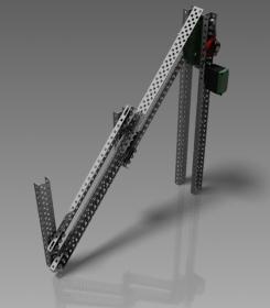
However that doesn’t mean I have stopped CADing; on the contrary. I’ve designed the new 8-bar lift design, which is a little thinner, and looks much better, and took jgraber’s reminder to me about keeping the large gear on the lower arm, so that the arm can be higher up, and thus raise higher. Here’s a screenshot of one of the sides:
I will be posting more pictures once I get the entire arm/mechanism assembly with the Lexan plate on the bottom and Rollers on the front and everything finished.
Hope you enjoyed, and as I said more CAD pictures to come soon!
~Jordan
Next step is put a sprocket on the same axle as the small gear, and drive it by chain from a motor in the base. CG can be lower and more centered this way.
Dont forget the elastic on each of the 4 bars.
AURA calls this layout “Scissor-lift in 4-bar mode.”
is that your whole tower?
or is it just half of it?
also, how does the CG look with the drive?
because it looks extremely tippy especially when you have game objects in the chute
ok nvm
i thought you extended the arm itself for more reach
but if its the same, then it should be fine
maybe its because you only have one side that it looks extra skinny and long
It has a total of 6 solid bodies, 3 of which are staying perpendicular to the ground (one of these is stationary,) and 3 are staying parallel to each other. It acts exactly like a 4-bar linkage, however it has 6 solid bodies rather than 4. Still not sure what to call it; I haven’t been able to find anything about it online, really. Double 4-bar linkage? Aperture have pretty much deemed that to their design, I’m pretty sure here.
Hey, im a bit confused on how this complex four bar linkage works. Since my team was thinking about different lift mechanisms that would be effective, i wanted to use something like this, i just dont full understand how it works exactly. would someone care to explain.
It’s pretty simple. Basically, it’s a four bar link with another four bar link stacked on top of it.
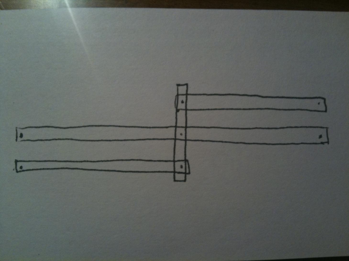
I attached a quick sketch I made that shows a side view. There are three horizontal bars. One shorter one below, a long middle one and another shorter one on top. The bottom and middle both pivot at the back of the arm. The middle also pivots at the front along with the top one. They are all connected together with a vertical center bar.
I hope I explained that well. If you have any further questions feel free to ask.
Hey that explaination helped a lot, i just have one more question. In the sketch that showed the side of the “double four bar linkage”, which bars are being driven by motors, and how many motors are recommended for this type of lift? Also which bars are “free” with no motor on them? And your explanaiton helped a lot and thanks.