Team 24C Super Sonic Sparks 2011-2012 Gateway Robot Reveal

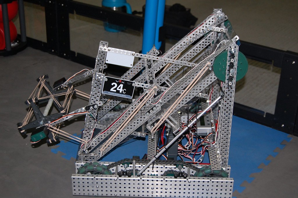
Thank you both! :slight_smile: I hope to be posting many more updates now, so here are a few more photos we took the meeting before last:

Arm fully raised, the bottom of the lift (at the end) reaches to over 35".

Almost fitting inside 18"x18"x18", just a couple axles to cut the ends off of.

Enjoy! :slight_smile:
~Jordan

downticks for:

  • only hexbar support of outer chassis rails
  • lack of linkage between independent arm motors
  • high CG battery location
  • Looks like gears at top of arm stick outside the 18" box

upticks for:

  • clean simple design
  • ease of maintenance of chain drive

Good luck

Have fun!

Looks solid, could use some things…:wink:

How long were the C Channel pieces you used? We are going to make a Parallel 6 Bar and I am wondering what lengths you are using. Thanks!

We used around 4 hexbars/standoffs to hold each side of the drive together, and they really seem to work well, in my opinion.
As for the lack of any linkage between the arms, as of now we have a single piece of aluminum holding them together on the end, and hope to add at least one more more towards the back.
The battery location is completely temporary, as is the c-channel piece which it’s sitting on. As of now, the c-channel has been moved, such that it is mounted on the floor of the drive, which will hold things together at the bottom, and also keep the center of gravity a bit lower. (Both batteries will be placed there.)
As for fitting inside 18"x18"x18", from what I’ve measured, it looks like we’re going to be fine. The closest dimension is probably the drivetrain going side to side, as it is very close to 18" with the screw-heads on the outside of the c-channel. The height is around 1/8" away from 18".

Yes, maintenance was key in this design. We wanted to be able to quickly and easily replace motors. The drivetrain is built so that even though we use the 12-tooth sprockets, we use collars so they can be somewhat easily slid out of the way in order to get to the drive motors. The motors on the arm are very easily accessible, as there is a straight path to both screw-heads from the outside.

Thanks! :slight_smile:
~Jordan

We used 1x2x1x35 c-channel pieces for the mounting-bars on the back of the robot. For the smaller, pivoting bars on the arm, we used the small aluminum 1x2x25 chassis pieces. Then, for the extra-long bar which reaches all the way down to the end of the arm, we mounted a 1x2x1x25 piece of c-channel to a 1x2x1x25 right-angle piece, with 4 of the holes overlapping, so a bearing block could be mounted in the center. (3 holes)

~Jordan

Thanks for the info!

Wow 35+". Im currious what the gear ratio is on your chassis. Looks great good luck this year.

Both quotes excerpted to remaining issues.
Let us know after the competition if the standoffs only between rails were sufficient for rigors of competition. I’ve had mixed luck with them. Maybe with nylon patch screws?
Notice that if you loosen the screws, the outer rail will slide around on the screw shafts, since #8 screw is .164" and the hole is .187". So it is only friction that is keeping this from sliding around. Potential fixes might be:
-grind down the end of the hex bars to fit exactly square .187" vex holes,
-drill out the ends of the hex bars to fit exactly the .187" shoulder bolt, and use those.
Either of these approaches used on both ends of the hex bars will provide a non-friction alignment between the inside and outside rails.

You didn’t mention the front to back 18" dimension, which is commonly overlooked, especially at the shoulder gear.
Your drive rails look like 35 hole = 17.5 inches.
The back edge of the vertical 1x2x1 look coincident with the back edge of the drive rails, and looks vertical.
The big gear at the shoulder joint sticks out beyond that in the back, and is the hind-most part of your robot; What am I missing?

Seems like the back edge of the vertical 1x2x1 is not at the very back of the drive pods. You can tell by the ways that the shadows are cast that there’s at least an inch of space behind them.
http://img546.imageshack.us/img546/6156/screenshot20111001at806.png
At least, I’m pretty sure that it clears. The other picture makes it look like it doesn’t.

Very nice. I don’t mind the high CoG battery position, actually; I like to have batteries in a place that’s nice and easy to reach and you’ve certainly achieved that. Then again, the pivot design we’re using has less CoG problems that this four-bar design, so maybe it is an issue.

Looking good so far, keep it up!

No problem!

Our drive is made up of two 3-wire motors and one 393 motor per side, geared up 1:2 to two 4" omni-directional wheels.

Thank you! Good luck to your team, as well. :slight_smile:

I’ll put a whole report on our robot after our first competition here, including things we may want/need to change, whether or not we think this general design would still continue to work well against others, problems we had, things we really liked about the robot while competing, etc.

I understand what you are saying, and thanks to your comments I have been thinking of possibly swapping out the screws for Shoulder Screws. We have some added spacers on the ends of the hex bars, so they may be able to work just right. Though, looking at it now, our robot has a large black spacer as well as a small one after each hex bar, and only a small one on each side would allow the shoulder screws to work, I think. Unless we can just barely squeeze some washers in there, and even possibly shorten the length between the outer and inner frames of the drive a little, which could be a good thing, as we are very close to 18" in that dimension right now.

Post below pretty much answers your question:
(Thanks, ThirteenTwo!)

Because of the position of our encoders, we didn’t have much choice on where to easily mount the vertical bars of the arms. But we were able to mount the bars into the robot a little, after we flipped the one encoder which was extending back further, and also shifted them both outward towards each side of the drive to create more room. After doing this, we can get the robot to just fit inside 18" in that dimension (front-back) with a little bit of … “adjusting”. :stuck_out_tongue_winking_eye:

I’ll be posting more pictures after tonight’s meeting. We’ve moved the battery position to lower towards the ground. Hopefully we’ll have the power expander on the robot by the end of the meeting. Still no bottom plate on the intake, however … I totally forgot to bring the Lexan piece home to heat it up in our oven… . :o So, unless we found out heat gun, we won’t be able to bend the Lexan and mount it on the robot until next meeting. :confused:

Again, thank you all for your comments/critiques. They are part of what helps our robot get better, and even help increase our (well, at least my) knowledge of our own robot.

So thank you all, and feel free to keep them coming. I’ll try to continue posting updates at least once a week, to go along with our meetings. (We’ll be meeting a little more often now, maybe a couple Saturday meetings, so we can get 24A up to speed, and hopefully get our robot finished as quickly as possible so we can move onto important things like Autonomous programming and :eek: maybe even driver practice before the tournament???)

Again, thanks. :slight_smile:
~Jordan

Do you have any videos of scrimmages with this robot, or practice’s?

Unfortunately, as this robot is not yet finished, we haven’t really run it much. So the only video we have is of us testing the intake: http://bit.ly/qQdNT0

But last meeting we added the Lexan, and the intake is nearly finished being positioned. (Still need to add stops for it, and allow it to start inside 18".)

I may post another video of the intake running with the Lexan plate on the bottom. We’re having a longer meeting this Saturday morning, so we’re ready for our tournament on the 29th, so hopefully the robot will be just about finished mechanically by then!

More updates to come!
~Jordan

Okay, so as it has been about a month since my last update, I thought I should post one.

24C recently went to its second tournament, which we hosted on October 29th. Here are some photos I took of it the night before the tournament:

Also, here’s the (nearly) completed CAD:

A view of all the crazy wiring:

I tried to neaten it up, but obviously it didn’t work so well… . :stuck_out_tongue: We were able to use the LCD display to create a menu we could select different autonomous modes from, before and during the autonomous period. However, we never ended up getting the robot to return to the starting tile after scoring so that we could select another, unfortunately. (We had it programmed to do so, but the turn never reached the spot it wanted to, because it probably slowed down a little too early.)

We strung surgical tubing over the batteries, Cortex, and sensors, to keep game objects from getting stuck there, and preventing our arm from lowering all the way.

At the tournament, 24C won its first 4 Qualification matches, but then had technical difficulties and no alliance partner in the 5th, losing that match, and then lost the next by a very close margin (1 point). After those two losses, we were able to pull out with wins in our next two matches, and ended in 4th place once Alliance Selection started. We were then picked by the #1 seed, team 3086Z, Cheese. They then picked 1727D, REX, and our alliance went on to be undefeated in the Elimination Matches.

As for Robot and Programming Skills, we found our robot to have a little trouble in picking up the stacks of game objects, so that’s something that needs to be worked on. We only got 15 points in Robot Skills, which was beaten with a 20 point score by 3086Z. We did, however, pull away with a win for Programming Skills, with 5 points. Once the awards were all being given out, 24C was also honored with the Excellence award. Let’s hope we can keep this up, and only continue to improve from now until April!

As always, we appreciate you all here on the VEX Forum, for your contributions through criticism and comments, and even for just reading through this.

Hopefully I will be posting another update soon, with CAD pictures of our new drive, so look forward to that!

~Jordan

congrats on all the awards you got in your second tournament!
we will have our first regionals this weekend
wish us luck!

just a quick question, why is your lexan “slide” so steep?
in other designs, that was the angle because it was the angle of their arm in its down position,
but in your case, you have a “hollow” 6-bar so the slide can have an even less of a slope (easier to pick up objects)

Thank you, and good luck to your team in your first tournament!

This is exactly what we were thinking. Thank you for pointing it out, as it is a big thing we’re working on changing before our next tournament on the 19th, and I forgot to mention it.

The reason it is so steep at the moment was because I didn’t want to have to make it hinge if it didn’t need to, and so in order to have the longest piece of Lexan possible, we put it at a 45 degree angle. However, as you said, it is more difficult to pick up objects, and also causes them to fall out the front much easier. This is why we’re hoping to swap the motors and Potentiometer to the outsides, so we can lessen the angle of the Lexan, and maybe even swap the Lexan back to aluminum, we’ll have to see. Then we’ll most likely add a hinged plate to increase our capacity.

Thanks for the post!

~Jordan

well if you look at it, lexan is flexible
so theres your “automatic hinge”
and you can have it start with a latch or something (steep) so it will fit in the box
but when you move and the latch gets unhooked, then the lexan will fall to its less steep position

thats what we have now, except its a “mini” version because we have an arm in the way :stuck_out_tongue:
it only gets “less steep” when the arm is raised

Ah. Yes, that’s a cool idea. I’m not sure how well we could get it working on ours. Really, we had to curve the Lexan to keep it from hitting things like our motors, because when it did, it caused the entire 6-bar to be pushed upward and forward, and made it impossible to keep it down all the way without any motor power, without some sort of a latch there.

Hopefully lessening the angle of the Lexan will keep the rollers from being able to push objects back out the front once we have more than 1. I think it should, but if not we’ll have to work on that. We were able to keep that from happening for 99% of the last tournament, but that took careful driving. It’d be better to have the drivers’ minds on other things, such as what we will do next, than having to be so careful when simply picking up objects. I do have to say that our two 6-bar and roller operators got pretty good at that (and they’re both Middle Schoolers in their first year on the team), even with less than 5 minutes each of practice driving the robot since the June 11th tournament.

~Jordan

even though i was one of those cleen sweep teams that had a intake roller dump design
i still dont like these to their precision and constantly turning with the rollers they become difficult to navigate and use

I strongly disagree. One of the great things about these guys is their wide intake angle. Even if you miss an object by six inches to one side, you can just turn while running the intake and it’ll pop in.

In fact, that’s the biggest advantage that these top-based roller intakes have over other intake designs. Certainly they require less precise aiming than the vertical intakes and they probably require less than the side-based roller intakes. It makes pickup easier and faster (and autonomous-able). Whether that’s worth losing the advantages of these other designs is your call.