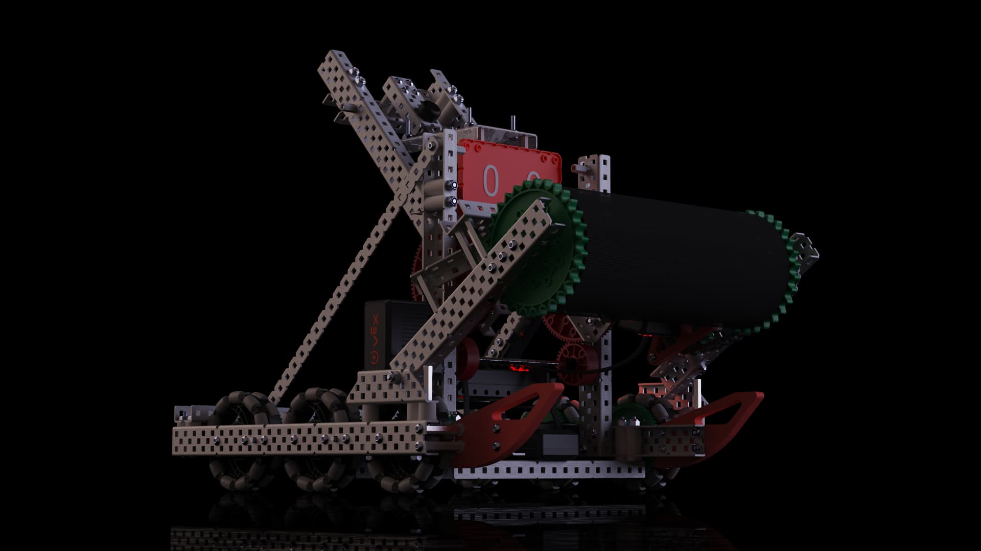
OWL Robotics and Paul Duke STEM High School are proud to present our Minimum Competitive Concept (MCC): M-O!
The name M-O was concieved based on one of the characters in the Pixar Movie WALL-E:
The term MCC is meant as a beginner-friendly robot that can be improved upon throughout the season while still being viable out of the box in the early steps of the competitive scene.
All of these subsystems are designed to be assembled separately and easily attached onto the main chassis. However, the keen eyed among you may have noticed there to be a few printed components in the model! This was intentional, as while the robot can still be used to mess around with and bounce ideas off of it, in order for it to be competition legal, teams must find a way to get rid of the 3D printed parts!
The robot also features a fairly solid fire-rate for matchloads, at nearly 22 Triballs fired within 17 seconds (that too at the “slappapult” running at only 75% it’s rated speed!)
If there are any questions about the robot or how it was assembled, feel free to post them below!
Yes, it has 3 illegal 3D-printed parts including the two sleds in front and the motor mount for intake. They have acknowledged this already. It is up to your team to find an effective yet legal alternative.
The CAD model can be opened in either Autodesk Inventor or Fusion 360 to access. However, we do plan on posting the .STEP file very soon in addition to the Inventor Assembly for teams to use.
We are also looking into finding feasible ways to have the model viewable in browsers. (psst BLRS Wiki )
There is a typo in the original post where the drive was noted to be 6 motors versus 4 motors (which is what it actually is). Unfortunately the new rules don’t allow me to edit the post.
For the gear, 24 teeth need to be shaved off, leaving 12 teeth intact.
It is possible to shave off less teeth and make 2 slip notches, allowing you to get 2 fires per motor rotation, but that also decreases the arc distance of the ‘slapapult.’ Again, something for teams to experiment with and expand on!
There is now a .STEP file in the Google Drive Folder. This should enable teams to open the model in any viewing software that can read .STEP files!
(Note that constraints will not exist when importing .STEP files, so if you would like to manipulate the model with constraints in place then you must use the inventor assembly file)
Hi! I just had a quick question about the firing rate of the “Slappapult”. The original post said that it is 42-RPM. If this is true, how did you fire 22 triballs in 17 seconds? Wouldn’t 42-RPM mean it would take just over 30 seconds to fire 22 times? I’m just curious, not trying to be accusatory (I saw the video in which it launched those triballs). Thanks in advance!
Watch the slapper. Notice that it doesn’t make a full revolution when it pulls back to hit the triball. The rate of fire is actually related to the speed of the slip gear, which, in this case, is 100 RPM. So under ideal conditions, this mechanism should actually shoot 100 triballs per minute.
I could be mistaken and missed something from in the Manuel but from a quick search you could possibly use string R7 e. An unlimited amount of rope / string, no thicker than 1/4” (6.35mm), or if you cut a hole then zip ties j. Zip ties that are identical in length and thickness to those included in the VEX V5 product line (4”
or 11” long). I would personally go with sting. please let me know if I missed something.