It looks like with latest pushbot news transmissions are popular again.
I would like to revive this topic and explain some interesting design options. But first we need to go over important background information about differentials:
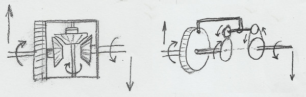
On the left is a classic differential and on the right is an alternative implementation of the same functionality. Believe it or not, but the differential in the following video, built by Stanley Shi and linked in many threads, offers exactly the same functionality, just with different parts.

Since there is no ring gear in VEX, it cleverly substitutes it with chain, but it is still just a differential.
The fundamental property of any differential with three mechanical inputs/outputs is that the sum of the changes over them always holds constant.
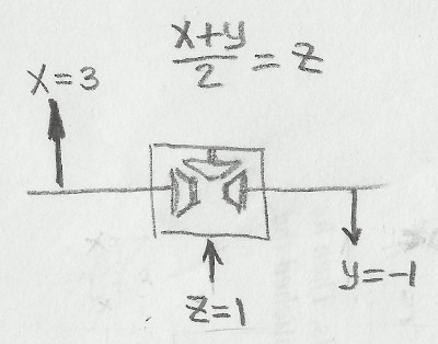
For example, if differential casing runs forward with angular velocity z=1 and the right side runs backward with y=1 then the left side will run forward with the velocity x=3, according to the formula (x+y)/2=z for a symmetrical differential. Even if you build something asymmetrical that would be obeying a formula 5x+3y=z you could still consider it a differential…
The angular velocity of the inputs are relatively easy to understand, but relationship between torques applied to differential inputs is a bit tricky.
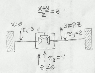
In the example above there are two resistive loads (wheels) attached to the left and right side of differential. Let say left one resists with a torque Tx=3 and right one with Ty=2. As you start applying mechanical power to the differential casing nothing will move until input torque Tz reaches 4 units, which is twice resistance of the right side 2*Ty. At that point you could expect angular velocity of y = 2z.
Left side (x) will not move until resistance on the right side reaches Ty=Tx=3. Then you would need Tz=Tx+Ty=6 in order to move both sides.
In case when you have a single load and two power sources the behavior is very similar. If one of the inputs is weak and doesn’t have enough torque to move the output then stronger motor will backdrive the weaker one, while the output remains stationary.
Now lets look at the following example of the double-differential “transmission” popular among Lego enthusiasts. There are a couple of videos of similar designs linked earlier in the thread. They are claiming to be multi-speed fully automatic transmissions. Unfortunately, they are not. I have analysed several designs and, even though they appear to “switch gears” under load, none of them offer more torque versus what you would have if you just used direct drive.
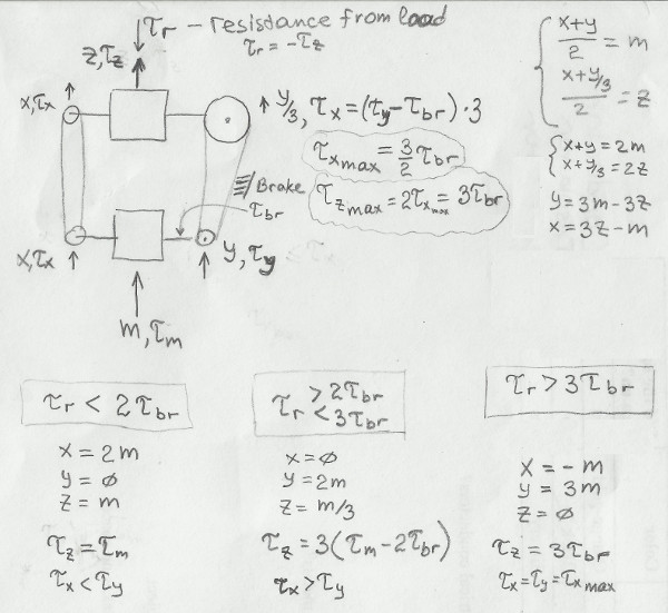
There are usually two differentials linking motor with the load through two power paths. On the above diagram left path is linked 1:1 and one on the right geared down 3:1. Also, the right side has some sort of friction pin or brake applied to it. There is a pair of linear equations for both differentials linking the velocities at various points: m, x, y, z. Where (m) corresponds to the motor and (z) to the output.
Tz = -Tr is the output torque to drive the load and Tbr is the breaking torque of the friction pin as measured at the right side of the bottom differential.
If load is very light the power flows through the 1:1 path on the left and output runs at z=m, x=2m, y=0. Then if output resistance (Tr) grows beyond a certain torque level (Tr > 2*Tbr), the right side path will have less resistance than the left side (Tx>Ty). The left side will stop (x=0) and the right side will start rotating delivering some power (y=2m) to the output (z=m/3).
As counter-intuitive as it is, the left side stops (x=0) because the torque Tx=3(Ty-Tbr) reflected through the top differential down to the left side of the bottom differential is greater than torque that motor is pushing into the right side (Tx>Ty). If torques on the two output sides of the differential do not match - only the weaker one will be driven.
Finally, if the load resistance (Tr) grows even further this drivetrain will no longer be able to drive it, because it max output torque (Tz max) is limited as it is related to Tbr. Then motor will simply circulate x and y gears wasting its power counteracting friction Tbr.
Here is a video of the prototype demonstrating demonstrating how it operates through the three different modes of operation:

The brake (a piece of zip-tie) touching the right chain is not very good as it still moves a bit - pretend it stays still at the beginning of the video. Then around 0:06 when I start holding the output (casing of the top differential) the left chain stops and the “transmission” enters low speed mode. Finally, as output is completely stopped you could see both both chains run fast. There is clearly much more torque available from the motor that it takes to stop the output.
Even on the paper if you try to pick a value for Tbr or change gear ratio you still could not get output torque to be greater than max motor torque, according to the formulas. Direct drive will deliver much better results than any friction based “transmission”.
In the next post I will describe how you can actually have both high speed and high torque modes with the aid of the ratchets or worm gears.