One dark night, after blowing the 13th port of a V5 brain due to static, our club finally snapped. After enduring hours of failing autons, lost matches, driver confusion, we officially had enough with broken ports. We decided to identify, and if possible, fix the problem. Our clubs journey led us to purchasing the parts needed to fix this particular brain, successfully restoring the brain to 20 of the original 21 ports after 13 ports were destroyed by static electricity. We also discovered some useful resources and tricks which may reduce static discharge on the robots. After seeing how widespread the problem of damaged ports on the V5 system is in both our competitions and the wider vex community, our club decided to document our discoveries about the issue.
What’s Going on Here?
As most people have deduced by now, static electricity is the main cause of damaged ports. To the best of our knowledge, static electricity is being developed between the metal frame of the robot, and the isolated plastic housings of the motors. Eventually this discharge builds to the point where it can jump to the data lines of the smart port, causing either the motor side or brain side RS485 transceiver circuit to fail. Static electricity is always built on frictional surfaces. Intakes, trays, or wheels can all be sources of static electricity in a robot.
How can We Stop It?
While Vex is now rolling anti-static mats, which should help with this issue, there are several fixes which could potentially help reduce static potential across a robot. First, apply an anti-static spray to all field tiles. This will discourage the build up of charge on the wheels. One example of static spray we have used is Here. Try to maintain metal-to-metal contact between components of a robot. Potential problem points here include screw joints and linear slides. These tend to be supported by bearing blocks, removing all metal interface. We tested this idea by screwing down a bare wire between each isolated component on our robot this year and while we continued to break ports, we observed a reduction in port damage.
About Those Damaged Ports
I must lead this section off with a disclaimer. Repairing V5 components in this manner is NOT condoned by the vex rulebook and is technically against the rules of competition, specifically those restricting modification of motors and brains. This WILL void the warranty of any vex product. All repairs of this nature are taken at your own risk. That being said, this repair will not change the performance of any ports and will not create an unfair advantage since this is only a part swap instruction. The repair in question will change the communications integrated circuit, called an RS-485 transceiver on either the dead brain or motor. This part of the circuit acts as a translator between the smart port wire and the processors in their respective product. These are common parts and can be found on websites such as digikey.com or mouser.com. The damaged chips are located on the V5 brain just under the cover. For our repair, we found the identical part at this Digikey link.
It is worth mentioning that this repair will not guarantee the restored function of a port. There is also a current limiting fuse for short can which can break, disabling a port. This occurrence is much less likely compared to the repair outlined in this post. We never experienced this. Due to the difficulty of soldering, we never attempted this repair. In our test repair, failures were due to soldering error damaging PCB pads.
Identifying Damaged Ports and Materials Required
With those disclaimers out of the way, I will first go through the repair process on a v5 brain. To complete this repair you will need to know how to do surface mount soldering. Useful soldering tutorials can be found at EEVblog #997 - How To Solder Surface Mount Components - YouTube and How and When to Use Solder Wick | DigiKey.
You will need a soldering iron with a fine tip, thin solder wire, flux of some form, solder wick and the RS-485 transceiver chips discussed earlier. First, identify all burnt-out ports on the brain by plugging in the brain to a battery, turning on the brain and plugging in a known working motor into each port. If the port is working as intended, the LED on the motor plug will be a solid red. If the port is broken, the motor led with blink and the motor will not be detected in the devices tab of the brain. Write down all damaged ports. It can be helpful to identify the ports later by placing cable ends in the damaged ports to identify them.
Repairing Ports V5
- Remove all power and cables from the robot brain, find the 4 screws in the back of the brain holding the two plastic halves of brain together. Remove these screws
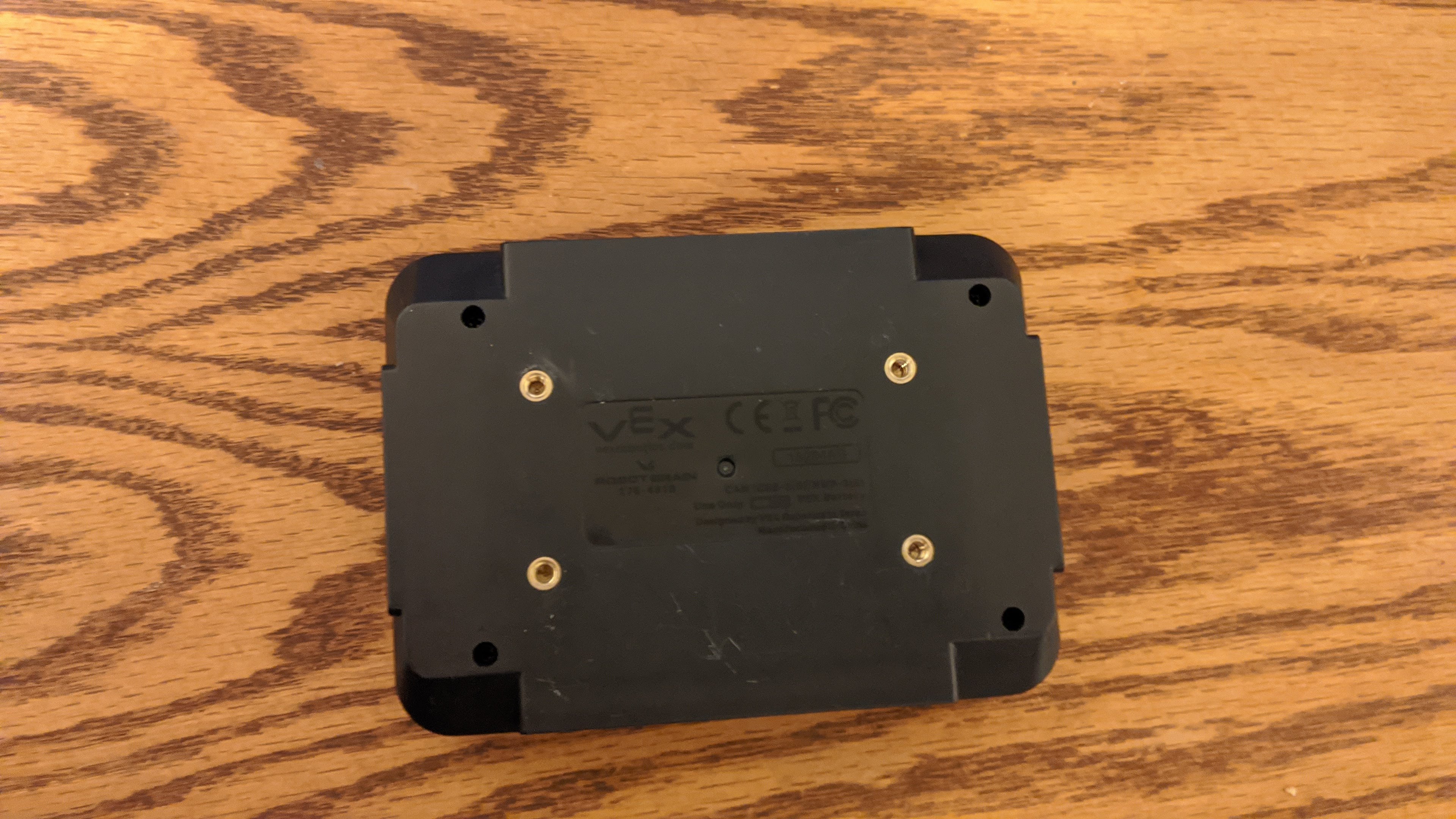
- After removing the screws, the clamshell frame halves can be separated.
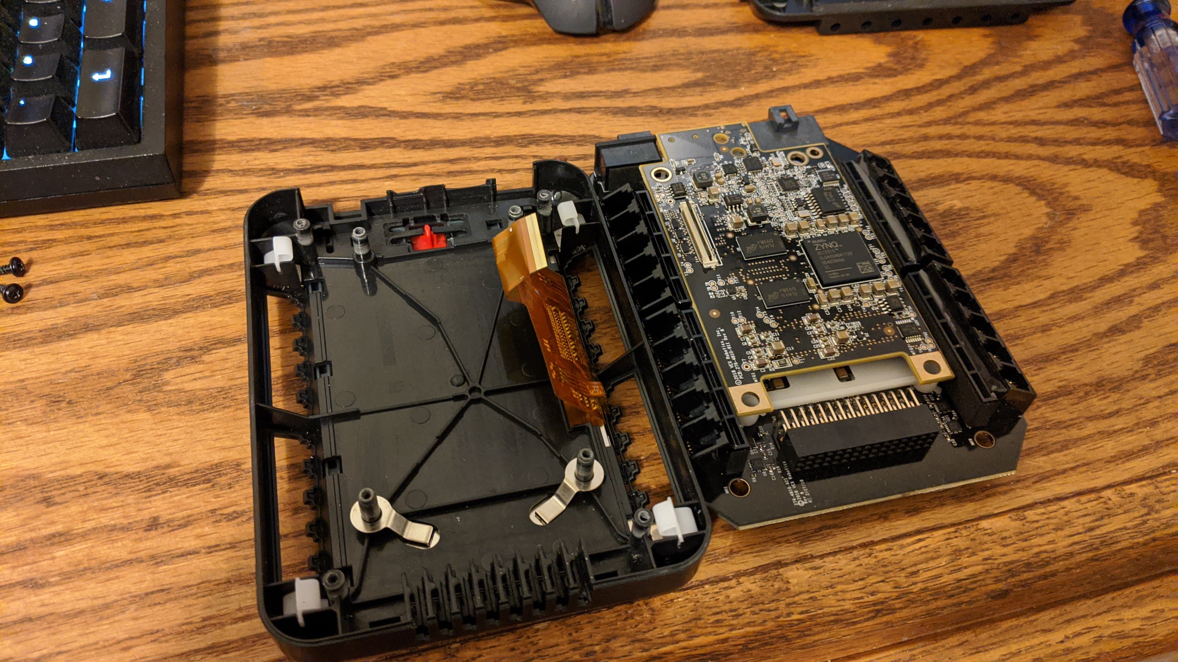
- Visible are the RS-485 chips we will be replacing. These are attached to the first of two circuit boards in the V5 brain. This board handles power distribution and communicates through a connector to the LCD and compute board of the brain. This board can be removed by gently pulling the board out of the brain at this point.

For this repair , I would suggest going no further into the brain unless you intend reflow solder components back on. This is an advanced soldering technique which I am not covering here as I don’t fully understand how to do it. There are a series of plastic parts in the board beyond the mounted parts which can fall out and be lost.
If you will reflow solder to replace the rs-485 chips, follow this paragraph. Due to the fact that a heat gun is used to remove components, you will need to fully remove the PCB from the ABS plastic case of the brain. If you do, first put the screen protector on, keep the screen on the table face down for the entire removal process. remove the four screws holding the board assembly in and take out the main board SLOWLY! There is a flex cable out of view which connects the screen to the main board! Pull the black tab on the opposite side of the flex cable and the board assembly can be removed from the flex cable. The top computational board can be removed by pulling gently and evenly on it. Remove it and the plastic spacer to reflow solder. Keep the screen face down as there are loose plastic and metal pieces present.
- Identify which chips are to be removed. If you marked the dead ports with cable ends, the ends will be in the smart port sockets in the front of the board. Use the solder wick to desolder the damaged chips and remove them.
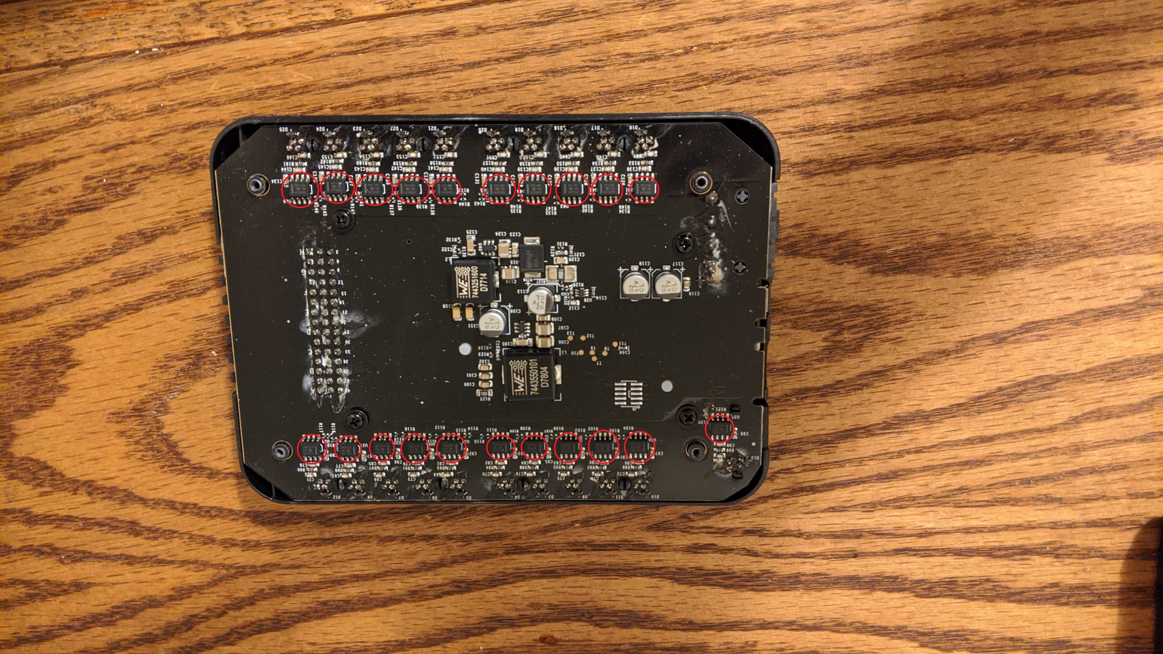
The bottom right port chip is port 21. The next chip to the left of this one of the above picture is port 10. The upper right port is port 20. The remainder of the RS485 transceivers on the brain follow port definitions on the exterior of the brain.
- Clean the pads carefully and tin the pads with solder.
- Place a new rs485 chip and solder the pins to the board. Check the orientation of the chip, the vertical bar printed on the side of chip should be on the same side as the other chips in its respective row.
- Check all the RS485 chips for bridged pins from soldering. A bridge occurs when solder connects two adjacent pins together instead of to their respective board pad. Touching the iron to these points will usually separate them. Failure to do this step could permanently damage ports or the brain.
- Reassemble the brain, replace all screws and power on the brain. The repaired ports should be functional. No further work is required. These devices are integrated circuits, and as such have no firmware.
So We Fixed It. Now What?
I now specifically want to address Vex Robotics. This is a real issue. I believe the design of V5 was intended to protect the larger brain, however the failures of these chips are drastically reducing the functional lifespan of the hardware, sometimes to less than a year. This is unacceptable for an educational robotics platform, especially one which fills this role so well.
One suggestion to the problem which requires little redesign would be to replace the existing RS-485 chips with a dual inline package variant with replaceable sockets. Vex could sell the replacement parts and when a port fails, it would be an easy to service fix for any team. Only four screws would have to be removed to implement repairs. Second, allow students to ground floating metal with wire. This would have helped this year with lifts and other mechanisms that often have floating metal. As I see it, it is not the student’s job with to compromise robot performance in order to not accidentally cripple their robot through static. I think simple repairs with the new anti-static field measures will have a beneficial impact on future years and students.
Edit: I relabeled the picture indicating chip port numbers, they were inverted.