This is a continuation of threads started by myself and vamfun during the summer.
Part 1
used a simple model to calculate motor current based on data gathered from a 269 motor in the form of a lookup table.
Part 2
used a more accurate model of the H-Bridge driver with estimated values for motor resistance and inductance derived from measurements of the pwm waveforms. This model was created by Chris Siegert (vamfun) with parameters based on my experiments, it was a lot of work that Chris started in a Chief Delphi thread a couple of years ago.
Chris used the estimated current as an input to a simulation of the motor PTC which he has made available here. I’m working on a rev 2 of the code presented there that is more suitable to add to existing projects. As part of this work I wanted to verify that the current model we have created matches reality. All the previous measurements I made were done using an oscilloscope with a non intrusive current probe. This is great for bench testing but not suitable to use with a robot being driven around. To allow these dynamic measurements I purchased some small current monitors based on the Allegro ACS711. Pololu conveniently has these available on a breakout board for $7 each.
http://www.pololu.com/catalog/product/2197

The ACS711 is easy to use with an analog input on the cortex, it has a voltage output that is proportional to the current flowing of about 167mV/A when powered from 5V. The current can be calculated by reading this value, removing the offset corresponding to 0A and scaling to convert from the digital value that the cortex gives to current. In ROBOTC code would look something like this (although the 2048 offset would differ slightly).
( (float)SensorValue( AcsPort ) - 2048.0 ) / 136.0;
The “136” is the scaling factor and is calculated as follows.
(4096 / 5) * 0.167
4096 is the full scale 12 bit output from the A to D converter in the cortex
5 is the voltage corresponding to the 4096 full scale value
0.167 is the voltage corresponding to 1A of current.
So this is all good, we can sample the actual current going to a motor by putting the ACS711 inline with one of the motor leads, however, there is one further thing we need to do before we can get an accurate reading. The threads I referenced above show some graphical representations of the current flowing through a motor, here is one example showing the current flowing in a stalled 393 motor with a command value of around 32 creating a 25% duty cycle.
https://vexforum.com/attachment.php?attachmentid=6580&d=1343620234
Looking at the yellow trace you can see that the current increases during the period when power is applied (when the blue waveform is at 0V) and decreases when power is removed. This process is repeated at 1150Hz for the VEX controllers. If we were to sample the current at a single instance using SensorValue we would read the instantaneous value of current which, in this case, would be a value of somewhere between 0.2A and 1.7A. What we really need is the average current, this can be achieved in a couple of different ways. The first would be to filter out these variations using an external analog filter between the ACS711 and the cortex. This would be a low pass filter that would reject the changing of current above a determined frequency, say 100Hz. The second way is similar but would use a digital filter in software. For my testing it was easier to go the digital route with a crude averaging filter where several samples are added together and then divided by the number used. The code to do this was as follows with the sample count being chosen through trial and error to match the duration of one pwm cycle.
    filtered_value = 0;

    for(i=0;i<40;i++)
        filtered_value += SensorValue( in2 );

    filtered_value = filtered_value / 40;
Using more samples will improve accuracy but uses more cpu time, there is also the small possibility of removing transient current information. For the purpose of these tests this small filter is sufficient.
The test code calculates current for the monitored motor and also samples actual current 10 times per second. Sampling more often would give smoother data but 10Hz is the speed I plan on running the code in the final software so seems reasonable. Data is sent to the debug stream and then copied to excel for processing. The first test done was with a 269 motor on the bench driven from port 10 on the cortex. A couple of issues came up, I’m not going to go into great detail but the first involves a situation where the motor command value is changing from negative to positive and the motor speed is still negative. The current calculation was creating a transient current spike that did not exist in reality. The code was modified to use actual motor direction rather than command motor direction for low values of motor commands. The second issue relates to the setting of the free running speed of the motor, this seems to be a critical parameter, if it was too low and actual speed rises above it then back emf is to high resulting in inaccurate calculations. Anyway, another modification to the code to address that. This graph shows the result of the bench test of the 269 motor, the x axis is time, the y axis current. The light blue trace gives an idea of what the command value was for reference.
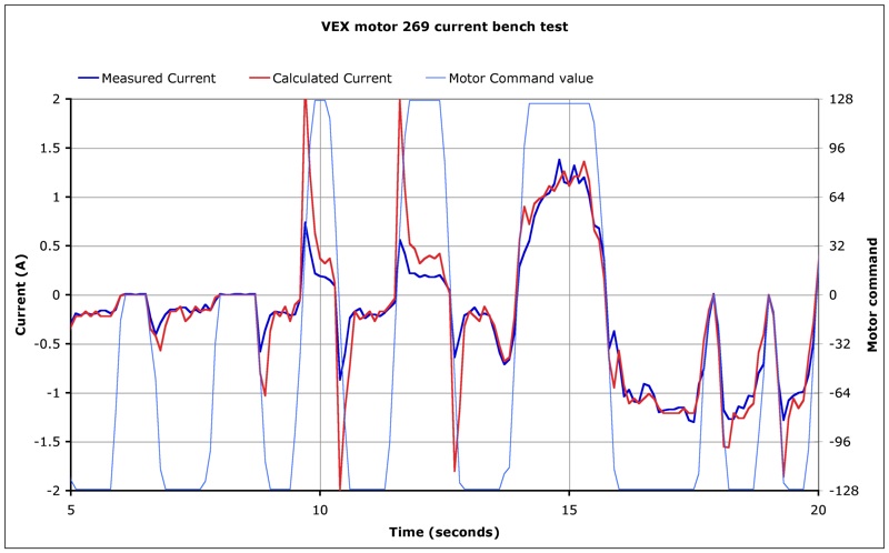
As this motor was just loose on the bench there is not a lot of load on it, you can see where I slowed it down at around 15 seconds. Not a bad match so next I installed the current monitor onto a 393 motor driving one wheel on a mecanum wheeled chassis I have.
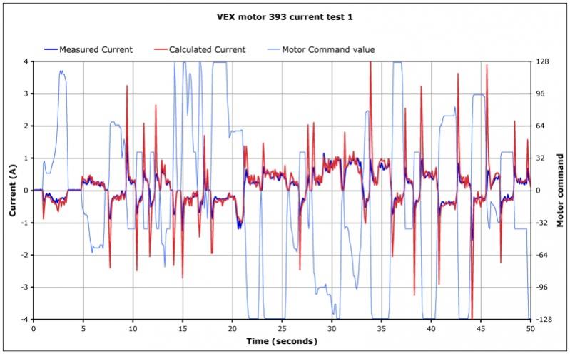
The 393 motor was on port 9 and being driven by a motor controller 29, the first test did not give a very good match between calculated and measured currents, the model was adjusted using a visual basic version of the algorithm in an excel spreadsheet. The free running current was reduced from the models default 370mA to 200mA and the free speed set to 110rpm, here are some results (it was a “reversed” motor so command values are opposite to the motor current ).
Normal driving (it’s a very light robot so not much strain on the motors)
Stalling the motor by holding the wheel.
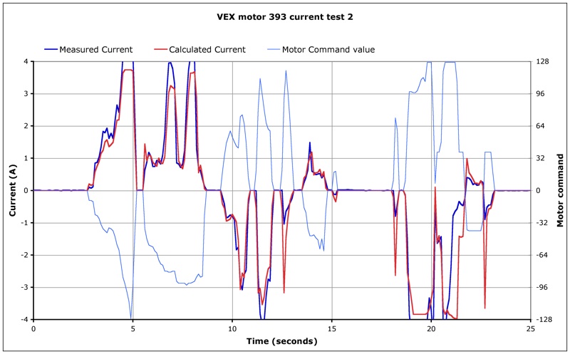
So my conclusion is that the model works, at least to the level of accuracy we need for the PTC monitor. There are some differences but these could be explained by the slow sample rate being used probably missing some current transients. The model is most sensitive to the value we are using for free speed, it could be improved by using a different value for forwards and reverse. Ideally parameters would be tuned for each individual motor but life is too short for that.
I will post revised code for the current calculation when I post the full smart motor library after ROBOTC V3.52 is released.